OPC UA driver for the REXYGEN system
(the OpcUaDrv module)
User guide
Plzeň (Pilsen), Czech Republic
2022-11-22
Contents
1.1 Introduction
1.2 Installation of the driver on the target device
1.2.1 Windows machines
1.2.2 Linux machines
1.3 Alternatives
2 Including the driver in the project
2.1 Adding the OpcUaDrv driver
2.2 Configuration dialog of the OpcUaDrv driver
2.3 OPC UA Client
2.4 OPC UA Server
3 Connecting the inputs and outputs and using function blocks in the control algorithm
3.1 Direct input and output signals
3.2 Function blocks
3.2.1 OPC UA Client
3.2.2 OPC UA Server
4 Examples
5 Troubleshooting
Chapter 1
The OpcUaDrv driver and the REXYGEN system
1.1 Introduction
This manual describes the OpcUaDrv driver for handling of communication over the OPC UA protocol within the REXYGEN system. The driver was developed by the REX Controls company.
OPC UA is an open communication protocol for industrial automation. Unlike legacy OPC, OPC UA is a multi-platform protocol, it may work as a web service and it offers many advanced functions like diagnostics, method calls and various levels of security and authentication in addition to standard events and data access. OPC UA is becoming a preferred communication interface of many devices from various companies.
OPC UA is not a suitable protocol for hard real-time communication between control devices, but is sufficient for soft real-time applications in many cases. A main utilization areas of OPC UA are human-machine interfaces and interconnection of various devices in a heterogeneous environment. See the OPC UA specification [1] for more details.
1.2 Installation of the driver on the target device
1.2.1 Windows machines
The target part of the driver, which is used for running REXYGEN OpcUaDrv on Windows 7/8/10 is included in the Development tools of the REXYGEN system.
1.2.2 Linux machines
If there is no RexCore runtime module installed on your target device, install it first using the Getting started guide of REXYGEN [2]. The installation includes all necessary drivers including OpcUaDrv.
If you want to install OpcUaDrv separately, it can be done from the Linux terminal using
the command
sudo apt-get install rex-opcuadrvt
1.3 Alternatives
Apart from the OpcUaDrv there is also a standalone OPC UA server for REXYGEN application. This application is connected to REXYGEN and exposes all the data signals defined in the REXYGEN algorithm as OPC UA Nodes. See OPC UA server – User guide [3] for more details.
In comparison to the OPC UA server for REXYGEN the OpcUaDrv lets user to include OPC UA blocks in the control algorithm to not only expose selected signals as a server but to also communicate with other devices as a client both through the OPC UA protocol.
Chapter 2
Including the driver in the project
The driver is included in the project as soon as the driver is added to the project main file and the inputs and outputs are connected in the control algorithm(s).
2.1 Adding the OpcUaDrv driver
The project main file with the OpcUaDrv driver included is shown in Figure 2.1.
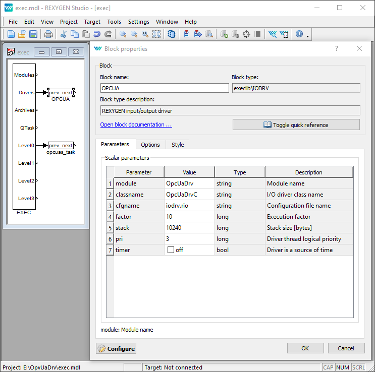
To include the driver in the project a block of type IODRV must connected to the Drivers output of the main EXEC block. The name of this block (OPCUA, see Fig. 2.1) must be used as a prefix of all blocks and input and output signals provided by this driver.
The most important parameters of IODRV block are:
- module – name of the module linked to the driver, in this case OpcUaDrv
- classname – class of the driver, which defines the role of the target device:
- OpcUaDrvC – for OPC UA Client
- OpcUaDrvS – for OPC UA Server
- cfgname – name of the driver configuration file, e.g. opcua_cfg.rio
- factor – multiple of the EXEC block’s tick parameter defining the execution period of the driver
The above mentioned parameters of the IODRV function block are configured in REXYGEN Studio program. The configuration dialog is shown also in Fig. 2.1.
The Configure button opens the configuration dialog of the OpcUaDrv driver, which is described in chapter 2.2.
2.2 Configuration dialog of the OpcUaDrv driver
The configuration dialog can be activated from REXYGEN Studio by pressing the Configure button in the parameters dialog of the IODRV block (renamed to OPCUA, see chapter 2.1).
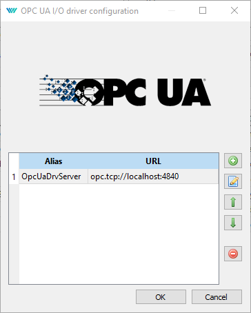
2.3 OPC UA Client
Single instance of the driver can process multiple client connections. The configuration dialog for OPC UA Client driver is shown in Figure 2.2 and has a form of a table of the client connections with buttons for adding, editing and deleting a connection. The configuration dialog for the client connection is shown in Figure 2.3.
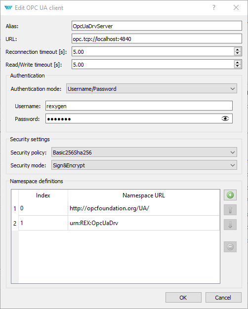
Client connection parameters:
- Alias
- – mandatory, Alias must be specified in the name of the flags and blocks that belong to the context of this connection.
- URL
- – address of the server
- Reconnection timeout
- – number of seconds to wait between connection attempts
- Read/Write timeout
- – number of seconds to wait for Read/Write operations to finish
- Authentication
- – section for authentication configuration
- Security
- – section for security configuration
- Namespace definitions
- – section for definition of the namespaces as they are defined
on the server
– Indexes of the namespaces are used to compose the NodeId parameter of the OPC UA blocks.
– During the initialization of the connection the namespaces defined in the table get resolved and the indexes on the client side get translated to the real indexes on the server side.
2.4 OPC UA Server
The configuration dialog for OPC UA Server driver is shown in Figure 2.4.
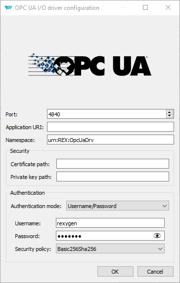
Server parameters:
- Port
- – port of the server
- Application URI
- – identifier of the application
– Application URI must be the same as the URI defined in the certificate used by the server.
– If a custom certificate is configured Application URI must be set to match. Leave empty otherwise. - Namespace
- – namespace to be used for all nodes
- Certificate path
- – path on the target device to a custom certificate to be used
- Private key path
- – path on the target device to a custom private key to be used
- Authentication mode
- – configuration of the authentication
– Anonymous – no authentication
– Username/Password – authentication by a username and password - Username
- – username
- Password
- – password
- Security policy
- – policy to be used as user token policy during authentication
Chapter 3
Connecting the inputs and outputs and using function blocks in the control
algorithm
The inputs and outputs of the driver must be interconnected with the individual tasks (.mdl files). The individual tasks (QTASK or TASK blocks) are connected to the QTask, Level0,…, Level3 outputs of the main EXEC block.
3.1 Direct input and output signals
The inputs and outputs of the OpcUaDrv driver can be accessed as shown in Fig. 3.1.
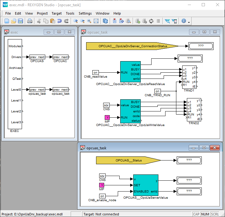
First block of the From type allowing the user to read connection status has the Goto tag set to OPCUAC__OpcUaServer_ConnectionStatus. Another block of the From type allowing the user to read status of the server has Goto tag set to OPCUAS__Status. The blocks always have the name of the driver block as a prefix right at the beginning of the tag followed by two _ characters (underscore). If the block belongs to the client driver the name of the driver with underscores must be followed by the alias of the client connection defined in the driver configuration dialog and another underscore.
3.2 Function blocks
3.2.1 OPC UA Client
The OPC UA Client driver is responsible only for maintaining the connection to the server. To read a value of an OPC UA Node over the OPC UA protocol the OpcUaReadValue block must be used. To write value an OPC UA Node the OpcUaWriteValue block must be used. The function blocks of the OpcUaDrv driver can be used as shown in Fig. 3.1. The blocks always have the name of the driver block prefix right at the beginning of the tag followed by two _ characters (underscore) and that is followed by an Alias identifying the client connection. To learn more about the OpcUaReadValue and OpcUaWriteValue blocks see [4].
3.2.2 OPC UA Server
The OPC UA Server driver is responsible for handling all the communication from the clients. To create and expose an OPC UA Node the OpcUaServerValue block must be used. The function blocks of the OpcUaDrv driver can be used as shown in Fig. 3.1. The blocks always have the name of the driver block as a prefix right at the beginning of the tag followed by two _ characters (underscore). To learn more about the OpcUaServerValue block see [4].
Chapter 4
Examples
To get started quickly the following examples can be used as a reference and you can modify them for your application.
- 0408-01 OPC UA Communication/OPC UA Data Exchange – The example demonstrates communication between a Client and a Server which are both implemented in REXYGEN.
Chapter 5
Troubleshooting
In the case that the diagnostic tools of the REXYGEN system (e.g. REXYGEN Diagnostics) report unexpected or incorrect values of inputs or outputs, it is desirable to test the functionality outside the REXYGEN system. There are many free programs that can be used for monitoring of the OPC UA communication such as UaExpert.
In the case that the given input or output works with other software tools and does not work in the REXYGEN system, report the problem to us, please. E-mail is preferred, reach us at support@rexygen.com. Please include the following information in your description to help us process your request as soon as possible:
- Identification of the REXYGEN system you are using. Simply export it to a file using the REXYGEN Studio (Target Licensing... Export).
- Short and accurate description of your problem.
- The configuration files of the REXYGEN system (.mdl and .rio files) reduced to the simplest case which still demonstrates the problematic behavior.
Bibliography
[1] OPC Foundation. OPC Unified Architecture Specification, 2020.
[2] REX Controls s.r.o.. Getting started with REXYGEN, 2020. .
[3] REX Controls s.r.o.. OPC UA server for REXYGEN – user guide, 2019. .
[4] REX Controls s.r.o.. Function blocks of REXYGEN – reference manual, 2020. .
Documentation reference number: 14711
2022 © REX Controls s.r.o., www.rexygen.com