OPC UA server for REXYGEN
Reference manual
Plzeň (Pilsen), Czech Republic
2022-11-22
Contents
1.1 OPC UA
1.2 OPC UA server for REXYGEN
1.3 Provided functionality
2 Address space
2.1 Blocks
2.2 Variables
2.3 Events
3 Quick start guide
4 Startup and configuration
4.1 Startup
4.2 System service
4.3 Configuration
4.4 Configuration sections
4.4.1 Target
4.4.2 Application
4.4.3 Security
4.4.4 User Token Policy (UTP)
4.4.5 Endpoint
4.4.6 Discovery
4.4.7 Options
4.5 Configuration templates
5 Authentication and authorization
5.1 Roles and users
5.2 Credentials INI file
6 Configuration Tool
6.1 Certificates
6.2 Authentication
6.3 Configuration examples
7 Connection testing with OPC UA clients
7.1 UaExpert
7.2 myScada
Bibliography
Chapter 1
Introduction
1.1 OPC UA
OPC UA is an open communication protocol for industrial automation. Unlike legacy OPC, OPC UA is a multi-platform protocol, it may work as a web service and it offers many advanced functions like diagnostics, method calls and various levels of security and authentication in addition to standard events and data access. OPC UA is becoming a preferred communication interface of many devices from various companies.
However, OPC UA is not a suitable protocol for hard real-time communication between control devices, but is sufficient for soft real-time applications in many cases. A main utilization areas of OPC UA are human-machine interfaces and interconnection of various devices in a heterogeneous environment.
1.2 OPC UA server for REXYGEN
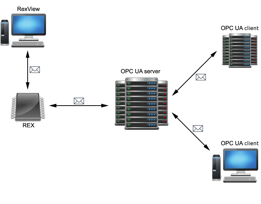
OPC UA server for REXYGEN is as standalone application that is connected to a REXYGEN runtime utilizing a low-level diagnostic protocol. It is not required to run the OPC UA server on the same station where the REXYGEN runtime is running. However, it is advised to run the OPC UA server as close to the REXYGEN runtime as possible to minimize latencies. The OPC UA server for REXYGEN implements the opc.tcp communication protocol, that is the most common protocol for OPC UA servers that acquire data from real-time control devices. The connection of OPC UA with client applications is shown on figure 1.1.
The OPC UA server for REXYGEN has to be licensed properly when it operates in an industrial environment. It is also possible to run the server in a so called DEMO mode, in which the server is fully functional but terminates after one hour without any notice. Licensing of the OPC UA server is performed by obtaining a valid license key and registering it either by using REXYGEN Studio or by setting the REX_LICENCE_KEY configuration parameter in the configuration file (see chapter 4.4.2).
1.3 Provided functionality
The OPC UA server is connected directly to a REXYGEN runtime core. It shows complete structure of a target algorithm (ie. blocks, variables..) in the address space. The server acquires complete structure of the algorithm during startup and make all runtime variables accessible to clients upon request.
A connection to the target device is maintained and checked periodically. The server tries to reinitialize the connection or reconnect to the target device when the connection is lost or an error occurs. Last acquired values are held and available to clients. Value quality is set appropriately. If the target algorithm is changed, the address space is rebuild appropriately and connected clients are notified.
Chapter 2
Address space
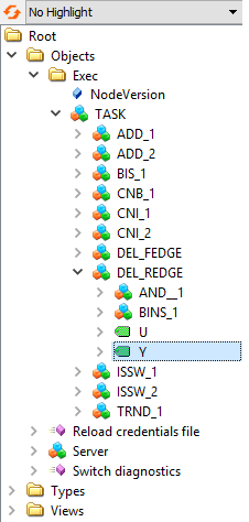
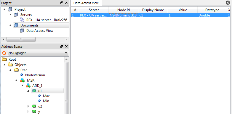
An address space contains all the data that is available to clients. Address space is comprised of nodes. Some nodes are common to all OPC UA servers, other nodes are application-specific. There are also nodes that control the server itself. The "Exec" node is a root node to all runtime-specific variables and the whole structure of a target algorithm (ie. tasks, subsystems, blocks and variables) is available underneath this node. A content of the "Exec" node is rebuilt when a connection with a target is established or a control algorithm is changed on the target. A sample address space is shown on figure 2.1. The picture has been taken from UaExpert OPC UA client (see chapter 7.1).
The server utilizes several name spaces. The first name space corresponds to the application URI and is dedicated for a server diagnostics.
The name space urn:Rex:TypeDeclaration is dedicated for definitions of types that are used among the address space.
The name space urn:Rex:Server is dedicated for commanding the server itself.
A name space that corresponds to the target algorithm is always target-specific and is described in chapter 4.4.2. This name space contains are all nodes that corresponds to the target algorithm.
2.1 Blocks
The structure of address space within the Exec node reflects the structure in a target device that the server is connected to. All nodes are part of the executive name space (see chapter 4.4.2). Node names published in BrowseName and DisplayName correspond to block names in the target device.
There are two distinct objects within the Exec node. The first object is a so-called block. A block represents a task (TaskType), a subsystem (SubsystemType) or a function block (BlockType) on the target device. The second object is a so-called variable. A variable represents a single input, output, state or parameter of a block.
2.2 Variables
Variables are represented by a data type, range and actual value. A range of a data type is stored in the Min and Max nodes. A value is the only node that is constantly synchronized with the target device.
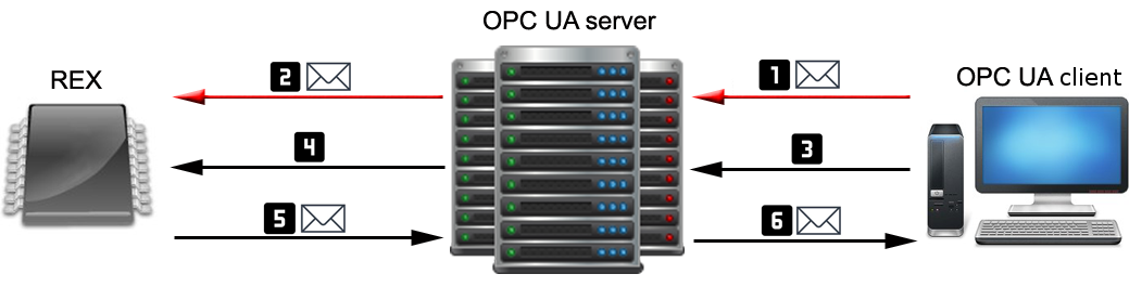
A value of a variable is propagated immediately to the target device upon a write request from a client. However, a cached value may be returned to a client upon a read request if a value age does not exceed specified limit. A maximal age of a value is configured by a SYNC_INTERVAL (see chapter 4.4.1). A variable is also refreshed periodically within this period if a monitoring is established by a client. The process of synchronization is shown on figure 2.2.
A data type of a variable object reflects the data type of a corresponding variable on the target. The names published in BrowseName and DisplayName correspond to the names of corresponding variables in the target device.
Note: Arrays and trend buffers are not supported in this version of the OPC UA server.
2.3 Events
A version number of a target executive is held internally by the sever. A GeneralModelChangeEvent event is invoked and list of added or removed object is passed on each time a change in the target executive is detected.
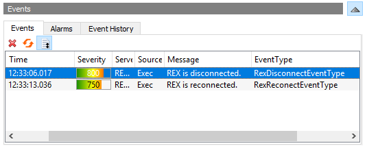
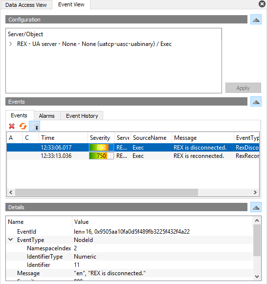
The server provides also an events for detection of communication failures. These events are inherited from DeviceFailureEventType and are available for the Exec node. An event RexDisconectEvent is called if the connection to the target device is lost. An event RexReconectEvent is called if a connection is established again. An event RexReloadEvent is called if an executive is changed on the target device.
Chapter 3
Quick start guide
A configuration file, server’s certificate and a private key (if encryption and authentication are required) are needed to successfully run a server. Following steps have to be done in order to start the server:
- Install REXYGEN system with the OPC UA server option enabled.
- Create a configuration file by following these steps:
- Create a certificate if you don’t have one either by using RexOpcUaConfig (see chapter 6.1), by using OpenSSL or by following certificate policy of your company.
- Set-up user accounts either directly or by using RexOpcUaConfig (see chapter 6).
- Set client certificate options if any of configured endpoint uses client certificates:
- Create certificate directories (by RexOpcUaConfig, see 6.1).
- Copy trusted client certificates into the folder specified by the CERTIFICATE_TRUST_LIST_PATH configuration option.
- Set discovery options appropriately if a discovery service is requested (see
4.4.6):
- Find out information about your discovery server.
- Copy discovery server’s certificate into corresponding folder.
- Set up configuration option in the DISCOVERY section.
- SERVER_URL - Endpoint URL of a discovery server.
- SECURITY_POLICY - Security policy used to communicate with discovery server.
- SERVER_CERTIFICATE_PATH - A patch to a certificate of a discovery server.
- ENDPOINT_URL - Endpoint list that is to be published on a discovery server. A single endpoint should be sufficient to register OPC UA server properly.
- Run the OPC UA service, see chapter 4.2.
Chapter 4
Startup and configuration
4.1 Startup
The server is configured by a simple configuration file. Its location is specified by the "-c" parameter.
RexOpcUa [-c <configFile>]
Path to the configuration file is set by default in GNU/Linux:
/rex/OpcUa/RexOpcUa.ini
Configuration options are described in chapter 4. The server may also run as a system service – see chapter 4.2). A quick start guide is available in chapter 3.
4.2 System service
The OPC UA server may run as a system service. The system service mode is a default and a recommended mode.
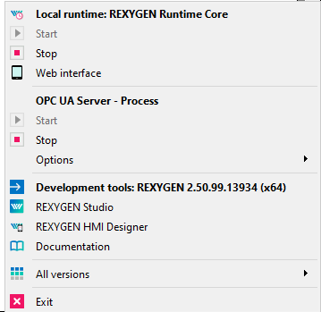
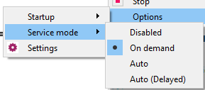
The OPC UA server running as a service may be monitored by a RexTrayMon application that runs in a system tray on Windows platform. (see pictures 4.1, 4.2 a 4.3). It is also possible to start, stop and run configuration utility from RexTrayMon

The OPC UA server runs as a system.d service on a Linux platform. The service may be started from command line using following command:
systemctl start rexopcua
Configuration file path for the server is defined by the CFGFILE option in a service configuration file:
/etc/rexcore/rexopcua.conf
4.3 Configuration
A configuration is stored in a standard INI file format. An UTF-8 encoding is preferred. The content is case-sensitive. There must be no additional space at the start and at the end of a line and around the "=" (equals) symbol. A comment is prefixed by a ";" (semicolon) symbol. A section name is specified within "[]" (square brackets) symbols. Every parameter must have a value. Parameters without values are ignored.
All sections must be identified by a name. A name must be recognized by the server. All recognizable section names are described in following paragraphs. Sections User Token Policy (UTP) Endpoint and Target may have subsections. A single corresponding endpoint or connection is created for every single subsection.
Configuration parameters are described in following paragraphs. Parameters that have a default value are optional. Parameter values may have string, number, arrays or boolean types. A number is always an integer. A boolean value is either Y, YES, ON for logical true or N, NO, OFF for logical false. An array is a set of several values within "[]" (square brackets) symbols divided by a "," (comma) symbol. An empty array is considered as a no value. A file path is a system path to the file. It is either absolute system path or relative to the configuration file.
4.4 Configuration sections
All supported section names of a configuration file are described in following paragraphs.
4.4.1 Target
This section contains options that affect a communication link established with a target device. Details are described in the table 4.2. There is a corresponding Exec node build for every single Target identified by a name defined by TARGET:Exec1.
| Field | Typ | Default value | Description |
| ADDRESS | IP address | – | IP address or DNS of target device that the server should connect to. |
| PORT | Number | – | (Optional) Communication port of the target device. |
| SYNC_INTERVAL | Milliseconds | 500 | Data synchronization period in milliseconds. |
| TCP_IDLE_INTERVAL | Milliseconds | 30000 | Idle notification period to the target in milliseconds. It should be shorter than 60000 ie. 60 seconds. |
| USERNAME | Text | – | (Optional) User name when authentication is required by the target. |
| PASSWORD | Text | – | (Optional) User password when authentication is required by the target. |
| USE_SSL | Y/N | N | Enables or disables secure connection using SSL. |
| CERTIFICATE_PATH | Optional | – | Path to a client certificate of the target device. |
| COMMUNICATION_DIAGNOSTICS | Y/N | N | Enable diagnostics of communication with REXYGENem. Create CommunicationDiagnostics object in Exec node. |
| COMMUNICATION_DIAGNOSTICS_WINDOW_WIDTH | Seconds | 10 | With of a window utilised for computation of floating average in diagnostics. |
| WHITE_LIST | Array | – | Parts of executive to be mirrored. Each part is equivalent to text identifier of NodeID of the mirrored node. |
| BLACK_LIST | Array | – | Parts of executive to be ignored. Each part is equivalent to text identifier of NodeID of the ignored node. |
| Field | Typ | Default value | Description |
| IGNORE_INPUTS | Y/N | N | Ignore blocks’ inputs. |
| IGNORE_OUTPUTS | Y/N | N | Ignore blocks’ outputs. |
| IGNORE_PARAMETERS | Y/N | N | Ignore blocks’ parameters. |
| IGNORE_STATES | Y/N | N | Ignore blocks’ states. |
When utilising WHITE_LIST a BLACK_LIST, the selected rule is also applied for child nodes (blocks, variables). A rule which is closest to a particular node is applied. If a node is explicitly mirrored then its parent nodes are created as well to preserve the organisation.
4.4.2 Application
The Application section contains main configuration options, see the table 4.3. Both the executive and server name space is configured in the Application section. The server name space is configured by a APPLICATION_URI parameter. The executive name space configuration has the following form:
urn:Rex:Exec:<COMPANY_URI_NAME>:<PROJECT_URI_NAME>: <INSTANCE_URI_NAME>:<TARGET_NAME>
Parameters COMPANY_URI_NAME, PROJECT_URI_NAME and INSTANCE_URI_NAME should be unique for each target device. Multiple OPC UA servers that are connected to the same target device should have these parameters set to the same value. The TARGET_NAME parameter matches the subsection TARGET (see the table 4.4.1).
Should the server run on the same device on which a REX runtime core is also running, the server may be licensed as a standard component of the REXYGEN system. Otherwise it is necessary to put a licensing key into configuration file by specifying the REX_LICENCE_KEY. If no valid license is present, the server terminates after one hour of operation. To get a licensing key, please contact the company and provide a device identifier ID – so-called Site ID. The Site ID is printed to the console during server startup.
| Field | Typ | Default value | Description |
| APPLICATION_CERTIFICATE_PATH | File path | – | Server’s certificate file path. |
| APPLICATION_PRIVATE_KEY_PATH | File path | – | Server’s private key file path. |
| APPLICATION_PRIVATE_KEY_PASSWORD | Text | – | (Optional) Password to the certificate file. |
| APPLICATION_URI | Server URI | – | Server’s URI that is used as a server name space. |
| REX_LICENCE_KEY | Text | – | (Optional) Licensing key. |
| COMPANY_URI_NAME | Text | – | Company identification. It is published in an executive name space. |
| PROJECT_URI_NAME | Text | – | Project identification. It is published in an executive name space.. |
| INSTANCE_URI_NAME | Text | – | Server instance identification. It is published in an executive name space. |
4.4.3 Security
The Security section contains configuration of clients certificates ie. validation options and locations. The section is relevant only when any of the configured endpoints has security options set.
The RexOpcUaConfig configuration tool from the REXYGEN installation may be used to create a server certificate and directories for client certificates.
| Field | Typ | Default value | Description |
|||||||||||||||||||
| CERTIFICATE_TRUST_LIST_PATH | Directory | – | Directory for client certificates that are trusted. |
|||||||||||||||||||
| CERTIFICATE_REJECTED_LIST_PATH | Directory | – | Directory in which all rejected certificates by the server are stored. Rejected certificates are not stored if this options is unset. |
|||||||||||||||||||
| CERTIFICATE_REVOCATION_LIST_PATH | Directory | – | (Optional) Directory for client certificates that have been revoked. |
|||||||||||||||||||
| CERTIFICATE_ISSUER_LIST_PATH | Directory | – | (Optional) Directory for certificate authorities |
|||||||||||||||||||
| CERTIFICATE_REVOCATION_CHECK_OPTION | N/L/S/A | N | Check of revoked certificates.
|
|||||||||||||||||||
| CHECK_SELF_SIGNATURE | Y/N | N | Checking of self-signed certificates. |
|||||||||||||||||||
| CHECK_CERTIFICATE_URL | Y/N | N | Certificate URL and client’s URL must match if enabled. |
|||||||||||||||||||
4.4.4 User Token Policy (UTP)
User Token Policy (UTP) sections define allowed authentication and authorization methods. The options are described in the table 4.5. Modification of user accounts and roles is described in chapters 5 and 6.2.
An authentication policy is specified by a client during connection handshake. No credentials are required within an anonymous connection. Otherwise a valid user name and password and/or valid and trustworthy certificate has to be supplied by a client. A certificate validation can be configured in the same way as a certificate validation for secured connection (see table 4.4).
A list of supported authentication policies has to be defined for every endpoint by the option USER_TOKEN_POLICY. An endpoint may support multiple anonymous policies. A client selects a required policy.
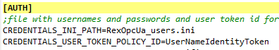
A configuration file with user roles, accounts and encrypted passwords has to be provided for username UTP. An optional parameter OPTIONAL_ENCODING_SALT defines an encoding salt of user passwords in the configuration file.
| Field | Typ | Default value | Description |
| USER_TOKEN_POLICY_TYPE | Anonymous, Certificate, Username | – | A type the policy. |
| AUTH_ROLE | Supervisor, Operator, Observer, AuthorizedUser, Anonymous | – | (Anonymous, Certificate) An assigned user role. |
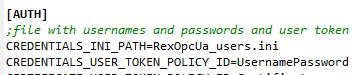
| CREDENTIALS_INI_PATH | File | – | (Username) A configuration file with user roles, accounts. |
| OPTIONAL_ENCODING_SALT | Text | q1we58 | (Username) Encoding salt for user passwords in configuration file. |
| CERTIFICATE_TRUST_LIST_PATH | Directory | – | (Certificate) Folder with trusted client’s certificates. |
| ... | ... | – | (Certificate) Another certificate validation parameters from table 4.4 can be used to configure the validation. |
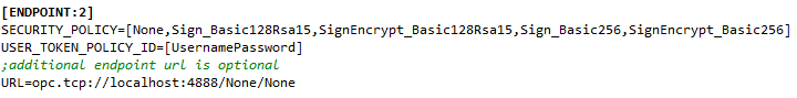
4.4.5 Endpoint
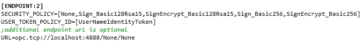
The Endpoint section contains configuration of OPC UA endpoints that are available for clients. Each subsection in the Endpoint defines a single endpoint and must therefore contain all required configuration options. All configuration options are described in table 4.6.
It is recommended not to use a local IP address for an endpoint when a discovery service is required to work. The endpoint address should have following form:
opc.tcp://<IP adresa | DNS>:<port>[/<endpoint>]
| Zabezpečení | Podpis | Šifrování | Algoritmus |
| None | Ne | Ne | – |
| Sign_Basic128Rsa15 | Ano | Ne | Basic128Rsa15 |
| SignEncrypt_Basic128Rsa15 | Ano | Ano | Basic128Rsa15 |
| Sign_Basic256 | Ano | Ne | Basic256 |
| SignEncrypt_Basic256 | Ano | Ano | Basic256 |
| Sign_Basic256Sha256 | Ano | Ne | Basic256Sha256 |
| SignEncrypt_Basic256Sha256 | Ano | Ano | Basic256Sha256 |
| Sign_Aes128Sha256RsaOaep | Ano | Ne | Aes128Sha256RsaOaep |
| SignEncrypt_Aes128Sha256RsaOaep | Ano | Ano | Aes128Sha256RsaOaep |
| Sign_Aes256Sha256RsaPss | Ano | Ne | Aes256Sha256RsaPss |
| SignEncrypt_Aes256Sha256RsaPss | Ano | Ano | Aes256Sha256RsaPss |
| Sign_Aes128Sha256nistP256 | Ano | Ne | Aes128Sha256nistP256 |
| SignEncrypt_Aes128Sha256nistP256 | Ano | Ano | Aes128Sha256nistP256 |
| Sign_Aes256Sha384nistP384 | Ano | Ne | Aes256Sha384nistP384 |
| SignEncrypt_Aes256Sha384nistP384 | Ano | Ano | Aes256Sha384nistP384 |
| Sign_Aes128Sha256brainpoolP256r1 | Ano | Ne | Aes128Sha256brainpoolP256r1 |
| SignEncrypt_Aes128Sha256brainpoolP256r1 | Ano | Ano | Aes128Sha256brainpoolP256r1 |
| Sign_Aes256Sha384brainpoolP384r1 | Ano | Ne | Aes256Sha384brainpoolP384r1 |
| SignEncrypt_Aes256Sha384brainpoolP384r1 | Ano | Ano | Aes256Sha384brainpoolP384r1 |
4.4.6 Discovery
The Discovery section configures a discovery service. The section is optional. The ENDPOINT_URL parameter may contain multiple endpoints that are to be discoverable by the service. However it is recommended to specify only a single endpoint. All other endpoints should be enumerable by a client through the single endpoint specified. The ENDPOINT_URL parameter should match at least a single endpoint on the server.
It is necessary to provide a valid URL of a discovery server, valid security options and a certificate location using SERVER_CERTIFICATE_PATH. A certificate should also be registered in the discovery server. Configuration parameters of a discovery service are described in table 4.8.
| Field | Typ | Default value | Description |
| ENDPOINT_URL | Array | – | (Optional) URL of a discoverable endpoint. |
| SERVER_CERTIFICATE_PATH | File path | – | A file path to the server certificate path. |
| SERVER_URL | URL | – | URL of a discovery server to which the OPC UA server is registered. The URL must start with opc.tcp://. |
| SECURITY_POLICY | Policy | – | Security policy used within the connection to a discovery server. A single policy must be used. The policy must be supported by the discovery server. For more information see table 4.7. |
| REFRESH_TIME | Milliseconds | 30000 | Registration refresh interval in milliseconds. |
4.4.7 Options
The Options section contains all other parameters that affect server’s behavior. These parameters should be modified only with detailed knowledge of OPC UA specification. All parameters in this section are optional and are described in table 4.9 and 4.10. All interval values are in milliseconds.
| Field | Typ | Default value | Description |
| MIN_SAMPLING_INTERVAL | Milliseconds | 600 | Minimal interval of sampling nodes. |
| MAX_SAMPLING_INTERVAL | Milliseconds | 10000 | Maximal interval of sampling nodes. |
| MIN_PUBLISHING_INTERVAL | Milliseconds | 500 | Minimal interval pro publishing data to the clients. |
| MAX_PUBLISHING_INTERVAL | Milliseconds | 600000 | Maximal interval pro publishing data to the clients. |
| MIN_SESSION_TIMEOUT | Milliseconds | 1000 | Minimal client session timeout. |
| MAX_SESSION_TIMEOUT | Milliseconds | 600000 | Maximal client session timeout |
| MAX_PIPED_PUBLISH_REQUEST | Number | 5 | Maximal count of queued requests for publishing. An error code TooManyPublishRequests is returned if the queue exceeds the limit. |
| MAX_NODES_TO_ANALYZE_PER_QUERY_REQUEST | Number | 100 | Maximal count of analyzed nodes in a single client request |
| MAX_DATA_CHANGE_MONITORING_QUEUE_SIZE | Number | 1000 | Maximal count of queued requests of monitored items. |
| MAX_EVENT_MONITORING_QUEUE_SIZE | Number | 1000 | Maximal count of queued requests of event items. |
| MAX_DATA_SETS_TO_RETURN | Number | 0 | Maximal count of data sets to return in a single request. |
| ENABLE_AUDIT_EVENTS | Y/N | N | Specifies whether an event should be fired if URL of a client does not match a URL in a certificate during creation, activation and cancellation of a session and during a service call. |
| Field | Typ | Default value | Description |
| ENABLE_DIAGNOSTICS | Y/N | N | Enables standard diagnostic objects on the server. |
| ALLOW_SWITCH_DIAGNOSTICS | Y/N | N | Enables enabling/disabling standard diagnostic objects by a client. |
| MIN_DIAGNOSTICS_UPDATE_INTERVAL | Milliseconds | 100 | Minimal interval for updating of diagnostic objects. |
| MAX_DIAGNOSTICS_UPDATE_INTERVAL | Milliseconds | 86400000 | Maximal interval for updating of diagnostic objects. |
| MAX_SESSIONS | Number | 0 | Maximal number of parallel sessions opened by clients, 0 for unlimited. |
| MAX_SESSIONS_PER_ENDPOINT | Number | 0 | Maximal number of parallel sessions opened by clients on a single endpoint, 0 for unlimited. |
| MAX_SUBSCRIPTIONS | Number | 0 | Maximal number of subscriptions created by clients, 0 for unlimited. |
| MAX_SUBSCRIPTIONS_PER_SESSION | Number | 0 | Maximal number of subscriptions per session, 0 for unlimited. |
| MAX_SUBSCRIPTION_LIFETIME | Number | 120000 | Maximal subscription lifetime. |
| MAX_MONITORED_ITEMS | Number | 0 | Maximal number of monitored items, 0 for unlimited. |
| MAX_MONITORED_ITEMS_PER_SUBSCRIPTION | Number | 0 | Maximal number of monitored items per session, 0 for unlimited. |
4.5 Configuration templates
Several configuration templates are provided to make it easier to configure a new instance of the OPC UA server. These configurations may be used as a quick start templates for arbitrary configurations. Following configuration templates are provided:
- Minimal - a minimal configuration with and unsecured endpoint and a running REXYGEN target on localhost,
- Secured_communication - a configuration for secured endpoints without authentication,
- Username_Authentication - a configuration for secured endpoints and authentication with user name and password,
- Certificate_Authentication - a configuration for secured endpoints and authentication with client certificates,
- Multi_Authentication - a configuration for multiple authentication policies,
- Endpoints - a configuration with two endpoints,
- Discovery - a configuration with registration to a discovery server,
- Licence - a configuration with defined licensing key,
- Full - a complete configuration.
It is recommended to always modify parameters ADDRESS, COMPANY_URI_NAME, PROJECT_URI_NAME and INSTANCE_URI_NAME.
Chapter 5
Authentication and authorization
5.1 Roles and users
Five roles are defined in the OPC UA server: Anonymous, AuthorizedUser Observer, Operator and Supervisor. An AuthorizedUser is allowed to browse address space. An Observer is also allowed to read values of variables and blocks. An Operator has all the permissions as Observer and is also allowed to write values of variables and blocks and thus affect behaviour of a target algorithm. A Supervisor has unlimited permissions including utilisation of communication diagnostics and invocation of server methods. Access permissions are listed in table 5.1.
| Permission | Supervisor | Operator | Observer | AuthorizedUser | Anonymous |
| Browse | X | X | X | X | |
| Reading values | X | X | X | ||
| Writing values | X | X | |||
| Reading permissions | X | ||||
| Communication diagnostics | X | ||||
| Method invocation | X | ||||
A role that is applied for a session is determined by a security policy that is applied on an endpoint and during authentication process. A client may only apply policies that are enabled and allowed on an endpoint. Security, authentication and authorization is ensured by a configuration of policies for endpoints, see chapter 4.4.5.
A valid path to a configuration file with roles, users and passwords has to be provided when authentication using user name and password is enabled. The configuration file is loaded during the server startup. Use RexOpcUaConfig tools to modify user accounts. This tool is integral part of REXYGEN installation.
5.2 Credentials INI file
The credentials INI file contains information about uses, their passwords and roles. This file contains five sections corresponding to OPC UA server roles: SUPERVISOR, OPERATOR, OBSERVER, AUTHORIZED_USER, ANONYMOUS. These sections contains pairs of users with encoded passwords. Passwords are encoded by SHA1 encoding of string: <username><password><OPTIONAL_ENCODING_SALT>. An example credential INI file is depicted bellow.
supervisor=718DA2408623AD7786E2E79AA700E8A8FBC49221
[OPERATOR]
operator=844BD4CBFF1FEF80251306E0E359243CC267DB2B
Chapter 6
Configuration Tool
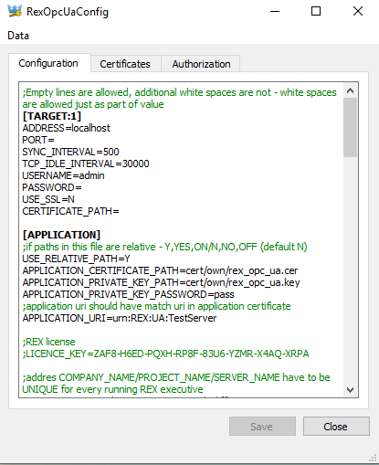
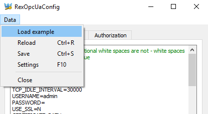
RexOpcUaConfig is a graphical configuration tool of the OPC UA server for REXYGEN. It simplifies a process of a server configuration. It provides a certificate generation, ini file modification and administration of user accounts. Several example configurations are provided for beginners.
A whole content of the configuration ini file is shown on the Configuration tab, see picture 6.1). A content may be modified by a user and saved. Configuration is checked for common errors before it is saved. All errors found are listed in the Errors tab.
6.1 Certificates
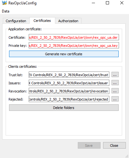
Administration of server and client certificates is provided on the Certificates tab, see picture 6.2. All file paths are obtained from the configuration file. The configuration file must be present and all file paths must be valid, otherwise the tab is filled with a red color.
Client certificates are stored among various directories. RexOpcUaConfig makes it possible to create, open and delete these directories. Trusted client certificates are stored in the Trusted folder. All certificates of clients that tried to connect to the server and were rejected are stored in the Rejected directory.
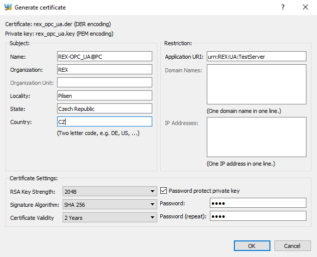
A special dialog is provided for certificate creation. The Passsword and Application URI fields are filled by values defined by APPLICATION_PRIVATE_KEY_PASSWORD a APPLICATION_URI configuration options.
The Subject field contains an arbitrary text. The Restriction field contains an IP address or domain that the certificate is bound to. The Application URI must match APPLICATION_URI configuration option. Certificate Settings affect certificate’s validity and used cipher.
A destination of generated file is is shown on Certificates tab, see picture 6.2. PEM and DER file format are used for generated certificate file and private key file.
6.2 Authentication
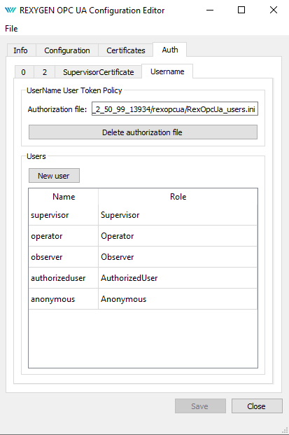
The Authorization tab (see picture 6.4) contains settings for authentication and authorization. The tab is visible only when the CREDENTIALS_INI_PATH is set and valid. All user accounts are stored in this configuration file.
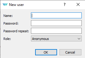
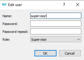
There is a simple graphical interface for creation of a user account (picture 6.5), modification (picture 6.6) and deletion.
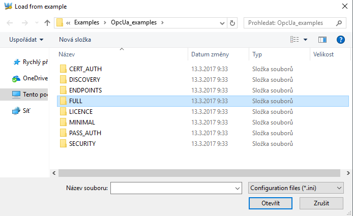
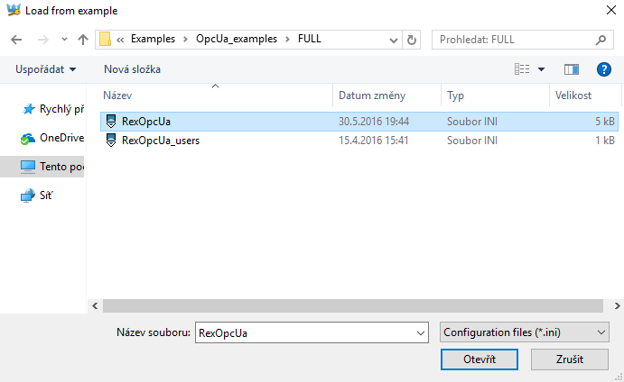
6.3 Configuration examples
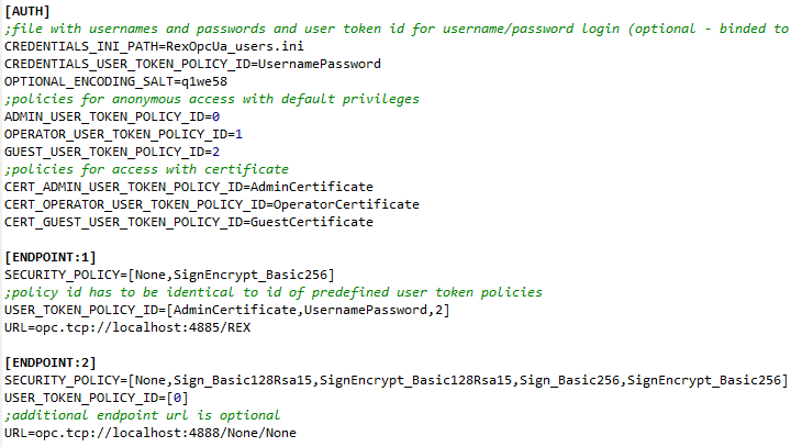
Several simple configuration templates are provided for beginners. (see chapter 4.5). An example configuration may be used as a quick start template for arbitrary configurations (see pictures 6.7, 6.8 and 6.9).
No template of configuration file for user accounts exists and the file must always be created from scratch. Please check, that OPTIONAL_ENCODING_SALT is set appropriately when copying or re-using the configuration file.
Chapter 7
Connection testing with OPC UA clients
Several OPC UA clients that are freely available may be used for testing of the OPC UA server. Their behavior and functionality may differ. UaEpert by Unified Automation GmbH and myScada are shortly introduced in this guide. Both anonymous and authenticated connections are demonstrated (see pictures 7.1, 7.2 and 7.3).
7.1 UaExpert
UaExpert is a universal and a fully functional OPC UA client that may be used for testing and verification of OPC UA connection and for a simple diagnostics. It supports wide range of OPC UA functionality.
UaExpert support three ways of authentication, encrypted connection, discovery service, reading data, writing data, monitoring of nodes, browsing address space, monitoring events, method invocation and more.
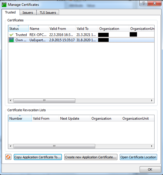
UaExpert invokes a certificate creation on a first startup. A generated certificate has to be copied to the server’s trusted certificates directory if an authentication using certificate is requested using option Settings > Manage Certificates > Copy Application Certificate To... (see picture 7.4).
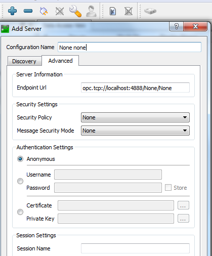
A connection with OPC UA server is established by clicking on "+" button. A dialog for connection configuration is opened. Advanced connection options are set in tab Advanced (see picture 7.5).
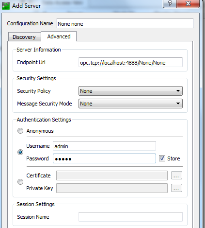
An established and working connection is indicated by a connected plug (see picture 7.7). A connection may be closed (unconnected plug) and re-established again. Connection options may be changed only in disconnected state (icon with a key). Authentication policy may be changed at any time (icon with a user). UaExper may have several connections established at the same time. Client configuration (including connections, monitored items etc.) may be saved and later loaded again.
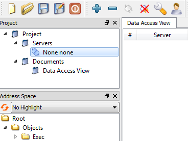
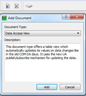
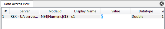
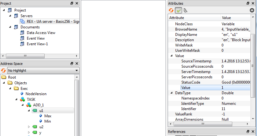
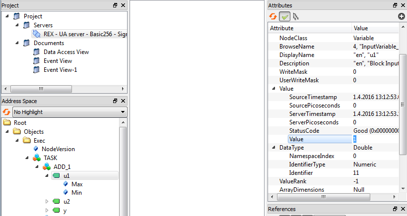
A Data Access View document has to be created by clicking on a document icon, selecting option Data Access View and then clicking on Add (see picture 7.8). To monitor an item simply drag and drop corresponding node from address space to the document (see picture 7.9). A monitoring of the item starts immediately. The item may be deleted at any time. A value may be written to a monitored item by double-clicking on the item in the document and entering new value(see picture 7.10).
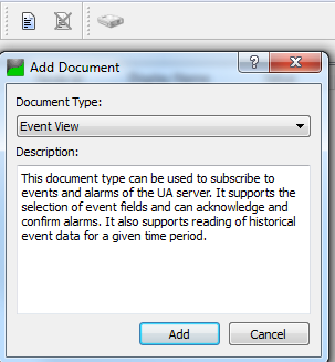
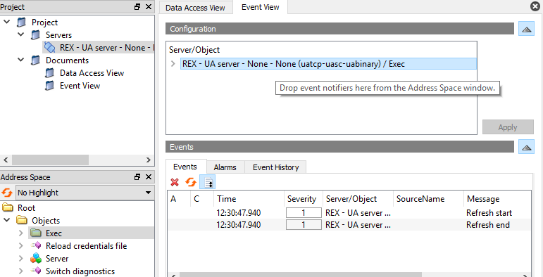
A Event View document has to be created by clicking on a document icon, selecting option Event View and then clicking on Add (see picture 7.11). To monitor an item simply drag and drop corresponding node from address space to the Configuration area (see picture 7.12). All monitored events are listed in Events area (see picture 7.13). Event details are shown in the Details area. It is recommended to always monitor the Exec and the Server nodes of the OPC UA server for REXYGEN.
A simple read operation in UaExpert is performed by clicking on a node in the address space tree view. A value is shown in the right part of the node, see picture 7.14. A write operation is invoked by double-clicking on a node, see picture 7.15.
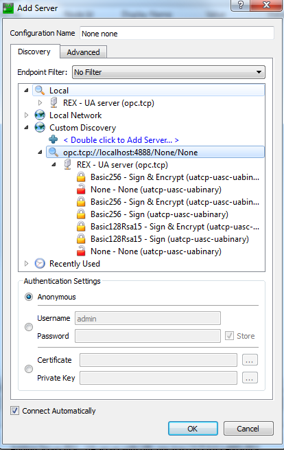
UaExpert supports a discovery service and shows all available OPC UA endpoints of registered servers (see picture 7.16). A user may expand a requested server in the tree view, select requested operation and set up an authentication policy to establish a connection. UaExper always checks a Local Discovery Server (LDS), a freely available discovery server (see chapter 4.4.6). Another option is to register a custom discovery server or OPC UA server directly.
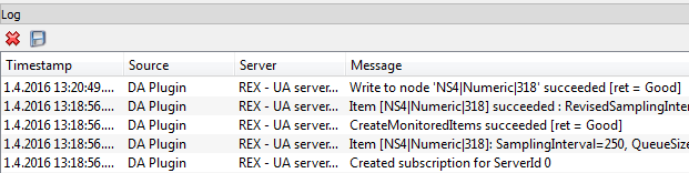
Inspect application logs that are available in the bottom panel (see picture 7.17) if a problem occurs with a connection.
7.2 myScada
mySCADA is an Human-Machine Interface tool that supports OPC UA. Not all OPC UA options are supported by mySCADA.
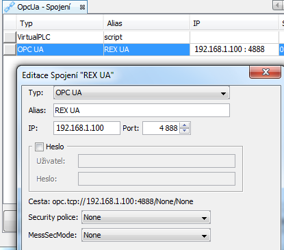
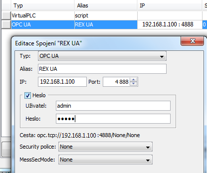
First, a new project has to be created in myPROJECT designer. Then open a connection tab, insert a new connection a select OPC UA. A configuration dialog is opened in which a connection with OPC UA is set, see picture 7.18.
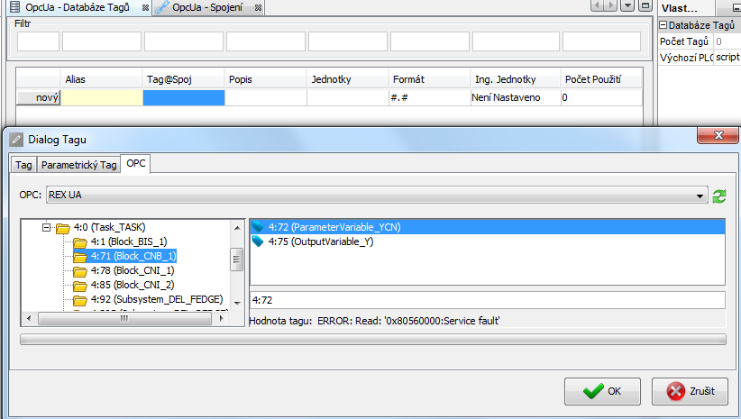
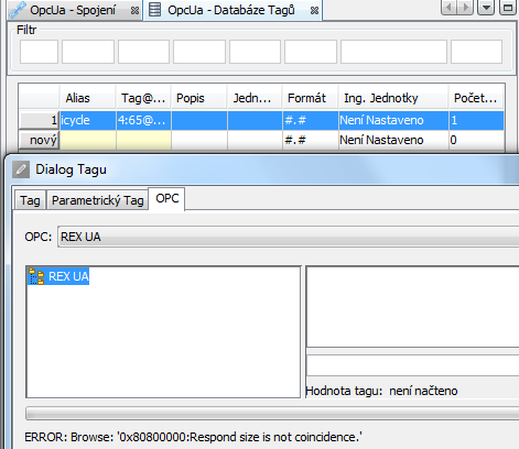
A data tag has to be defined in the next step. The tag contains a reference to a single node on OPC UA server that contains the requested value, see picture 7.19. The tag may be then used to show a value in HMI application, see picture 7.20. Download a final project to the device and use myView to show it.

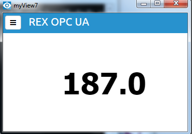
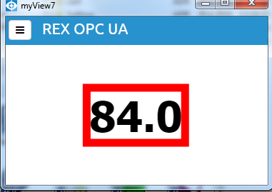
Use myView to show HMI on a device. A proper value is shown and updated from OPC UA server, see picture 7.21. An error is indicated when a connection error occurs, authentication fails or a tag is not valid, see picture 7.26.
An endpoint has to have a /None/None suffix to mySCADA work properly with unencrypted connection. A policy ID for anonymous login must be set to zero, see picture 7.1.
To configure user name and password authentication policy a UserNameIdentityToken policy has to be set (see pictures 7.23 and 7.24) and user name and password must be supplied (see picture 7.25).
An error is indicated when authentication fails, see picture 7.26.
Bibliography
Documentation reference number: 14711
2022 © REX Controls s.r.o., www.rexygen.com