REXYGEN Studio
User guide
2022-11-22
Plzeň (Pilsen), Czech Republic
Contents
1.1 Starting REXYGEN Studio
1.2 Working Area
1.3 Application Modes
1.4 Main menu
1.4.1 File
1.4.2 Edit
1.4.3 View
1.4.4 Project
1.4.5 Target
1.4.6 Tools
1.4.7 Settings
1.4.8 Window
1.4.9 Help
2 Function blocks
2.1 Using Function Blocks
2.1.1 Function Blocks Reference
2.2 Block Properties
2.3 Common Block Properties
2.4 Connecting Blocks
2.5 Persistent memory
3 Compile, Download and Diagnose Your Project
3.1 Project Compilation
3.2 Downloading Project
3.3 License Activation
3.4 Watch mode and Diagnostics
3.4.1 Monitoring signals
3.4.2 Viewing trends
3.4.3 Viewing REXYGEN System Log
3.4.4 Diagnostics
4 Creating a Library of Reusable Components
4.1 Creation of a Subsystem
4.2 Declaration of Subsystem Parameters
4.3 Moving the Subsystem to a Library
5 Using User-Defined Libraries of Reusable Components
5.1 Including a Library in Your Project
5.2 Using Function Blocks From a Library
5.3 Detaching a Library Reference
6 Supported Operating Systems
7 Keyboard Shortcuts
8 Other Important Features and Tools
8.1 Human-Machine Interface
8.2 REXYGEN HMI Designer
8.3 REXYGEN Diagnostics
Chapter 1
Introduction
REXYGEN Studio is a graphical tool designed for a creation of real-time control algorithms with the support of a large function block library of the REXYGEN system [1]. A developer may utilize many function blocks from simple comparators and timers to advanced and specialized blocks designated for analog signal processing and regulation. There are various specialized regulators including PID regulators with automatic tuning of parameters. Any algorithm developed in the REXYGEN Studio may be instantly compiled and downloaded into arbitrary target device (Linux IPC, WAGO PFC 100/200, Raspberry Pi, Pigeon PLC, UniPi Neuron/Axon/Patron, etc.). After the algorithm is successfully compiled and downloaded to the target device, it is possible to switch REXYGEN Studio to a Watch mode in which all parameters and variables of all function blocks may be inspected or adjusted. A connection may be established locally or over Internet using standard protocol IPv4 or IPv6. A secure connection over SSL protocol is supported.
A detailed documentation for function block library may be opened at any time with the F1 key. The documentation is installed automatically in the default setup configuration and we advise not to uncheck it.
1.1 Starting REXYGEN Studio
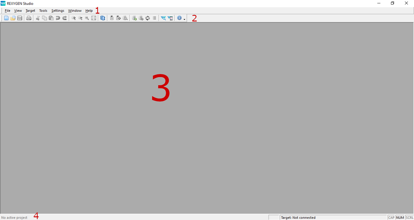
The REXYGEN Studio development tool may be started without any parameters by double-clicking on its icon in a start menu of Windows. A main window of REXYGEN Studio consists of four main parts: a main menu (1), a toolbar (2), a working area (3) and a statusbar (4). There may be several files opened in the working area simultaneously. A name of opened and active file is shown in the title of REXYGEN Studio main window with an asterisk when there are unsaved modifications.
1.2 Working Area
A working area is a main area where windows with opened project files are placed. Files with function block diagram have a file name extension .mdl. A zoom operation is supported. Zoom in/out operations may be performed using a mouse wheel while keeping the Ctrl key pressed, clicking on those commands in the menu or in the toolbar and also by pressing the keys F2 and F3.
1.3 Application Modes
The application provides two modes: a Development mode and a Watch mode. An algorithm is developed in the Development mode by drawing function block diagram on the canvas and by configuring function block parameters. The application may or may not be connected to a target device.
When connected to the target, the application may be switched to the Watch mode. In the Watch mode, the developed application can’t be modified. Instead, the function block diagram serves as a diagnostic interface to the running algorithm. User may inspect all signals, parameters, trends and detailed diagnostics of the target.
1.4 Main menu
1.4.1 File
The File menu provides commands which are connected with files.
- Start: Opens a simple start dialog with multiple options that are available at the beginning of developing a control algorithms with REXYGEN Studio. The option is available only if no project is opened.
- New: Creates a new diagram file.
- Open: Opens an existing diagram file.
- Close: Closes an active file.
- Close All: Closes all opened files.
- Save: Saves an active file.
- Save as: Saves an active file under a new name.
- Save all: Saves all opened files.
- Start with a Plain Project: Creates and opens a new plain project.
- Start from an Example Project: Opens a dialog in which a user may select an example project that is provided within installation of REXYGEN. The selected project is copied into specified directory and opened. A user may start developing a new application by creating a new project from one of these examples.
- Open Project from Target Device: Storing of project source on target device is supported starting with REXYGEN version 2.50.4. If a project is stored on a target device, a user may upload it back to the computer and open it using this option.
- Export: Exports an active file to SVG format.
- Set as Project Main File: Selects an active file as a main project file.
- Save Project as: Duplicates an opened project into another directory, closes an opened project and re-opens it from the new location.
- Print: Prints an active file.
- Print Preview: Shows print preview before printing.
- Print Setup: Shows printing options.
- Exit: Closes all files and exits REXYGEN Studio.
1.4.2 Edit
The Edit menu provides commands which are connected with objects and function blocks.
- Undo: Discards last editing operation.
- Redo: Restores discarded operation.
- Select All: Selects all object in an active window.
- Cut: Cuts selected objects.
- Copy: Copies selected objects into a clipboard.
- Paste: Pastes objects from a clipboard.
- Properties: Shows properties of selected objects.
- Declaration of Parameters: Displays a dialog for declaring parameters of subsystems.
- Open Subsystem: Opens a selected subsystem in a new window.
- Create Subsystem: Create a new subsystem from selected blocks.
1.4.3 View
The View menu provides commands and operations with REXYGEN Studio windows and working area.
- Toolbar: Show/hides the main toolbar.
- Statusbar: Shows/hides the statusbar.
- Zoom In: Zoom in within an active window.
- Zoom Out: Zoom out within an active window.
- Zoom to 100 %: Shows an active windows in default zoom scale.
- Zoom to Fit: Zoom an active window so that all object fit to the screen.
- Block Library: Opens a library with function blocks.
- Compile window: Shows a window with all messages from last compilation.
1.4.4 Project
The Project menu provides commands for project compilation, download, activating the Watch mode and watching signals.
- Compile: Compiles an active project into a binary configuration.
- Compile and Download: Compiles an active project and downloads the binary configuration into specified target if compilation is successful.
- Activate Watch Mode: Activates the Watch mode of REXYGEN Studio. A connection dialog is opened if REXYGEN Studio is not already connected to a target device. The Watch mode is indicated by a gray background of diagrams. A user may start monitoring signals after the Watch mode is activated. REXYGEN Studio remains connected to the target even if switched back to Development mode and all diagnostic data acquisition tasks continue in background.
- Watch Selection: Starts monitoring blocks that are selected.
- Exclude from Watch: Stops monitoring blocks that are selected.
- Signal to Watch: Shows a signal tree and advanced options for signal monitoring.
- Check Parameter Changes: User may check parameter changes made in the Watch mode anytime until the Watch mode is left. User may apply such changes back to the drawing or discards them.
1.4.5 Target
The Target menu provides commands for communication with a target device, signal monitoring and detailed on-line diagnostics. Some commands are available only when a connection with a target device is established.
- Connect: Connects to a target device. The user is asked for target address and connection options. The application remains in Development mode.
- Disconnect: Disconnects from a target device and switches to Development mode.
- Identify: Shows target version and identification parameters of running project.
- Show System log: Downloads and shows messages from REXYGEN system log on a target device.
- Configure System Log: Shows a dialog for configuration of REXYGEN system log on a target device.
- Diagnostics: Shows a window with detailed diagnostics of a target device.
- Backup: Offers a way of creating a backup of a control algorithm that is stored on a target device. A user specifies a local file name into which the backup is stored. These components of control algorithm are stored into a backup: executive, human-machine interface and project source (if project source is stored on the target). A text file is created beside the backup that contains a detailed information about the content of the backup.
- Restore: Offers a way of restoring a control algorithm from a backup file to the target device. The operation is very similar to a download operation but a user may specify a file name of a backup.
- Change password: Shows a dialog in which a password of a current user may be changed.
- Licensing: Shows a dialog in which active licensed options are shown and a user may eventually add or modify licensing keys.
- Web Interface: Opens a web interface of a target device in a user’s default web browser.
1.4.6 Tools
The Tool menu is a shortcut for launching another tools available within REXYGEN.
- REXYGEN Diagnostics: Launches REXYGEN Diagnostics, a diagnostic tool for detailed inspection of running algorithm on a target device.
- Cam Editor: Launches an editor for cam profiles and curves.
- SFC Editor: Launches an editor for finite state machine. relevant function block is called ATMT.
- REXYGEN HMI Designer: Launches REXYGEN HMI Designer, a tool for a simple creation of web-based Human-Machine Interface (HMI).
1.4.7 Settings
Dialogs with global and diagnostics options of REXYGEN Studio are accessible within the Settings menu.
1.4.8 Window
The Window menu offers operations for arranging opened windows.
1.4.9 Help
- Function blocks manual: Shows a detailed documentation for all function blocks that are available in the function block library of REXYGEN.
- Examples: Shows all available examples and templates.
- Documentation: Shows a list of documentation and manuals that are available for REXYGEN.
- About REXYGEN Studio: Shows a version information about the REXYGEN Studio.
Chapter 2
Function blocks
All function blocks in the function block library of REXYGEN are described in the reference manual [1].
2.1 Using Function Blocks
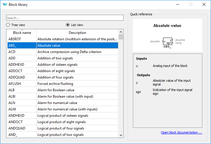
All function blocks that are available in REXYGEN and that may be added into a function block diagram are accessible within a function block library dialog that is shown from menu View/Block Library or by Ctrl+L shortcut.
By default, the library is in Tree view mode where the blocks are organized in sublibraries. Their location is always denoted as sublibrary/block, e.g. LOGIC/AND_ for the logical AND block in the LOGIC sublibrary. Inside a sublibrary, the blocks are ordered in alphabetical order. It is also possible to switch the library to List view mode, where all the blocks are sorted alphabetically, regardless of the sublibrary they belong to. You may search for a particular function block by typing a name or a part of a name.
Blocks are added to the diagram by simple drag and drop operation. Both the symbol of a block and the name of a block may be dragged.
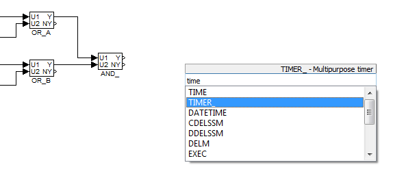
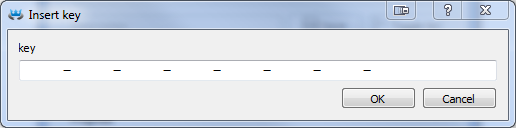
Another approach to adding function blocks is the so-called Quick insert feature. Just start typing the block name anywhere in the diagram and a list of matching function blocks will pop up. Clicking the function block of your choice will add it to the diagram.
2.1.1 Function Blocks Reference
A detailed description of a selected block is invoked by the F1 key or by selecting the Help from its context menu. A HTML documentation is opened by default. If the HTML documentation is not available (it was deselected during installation), REXYGEN Studio tries to open a PDF documentation and a user must scroll down to the corresponding block manually.
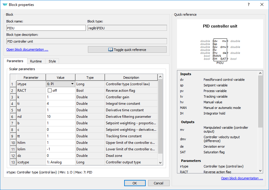
2.2 Block Properties
All block properties can be modified using properties dialog. The dialog is invoked by double-clicking on the block in Development mode, by pressing the Ctrl+E shortcut or by selecting Edit/Properties from the menu. Dimensions of a block on the canvas may be changed with a mouse by first clicking on the block a then dragging any of highlighted corners. A block may be moved by mouse or by keyboard arrows while the block is selected. The block may be rotated using the Ctrl+R shortcut.
Properties that may be modified by the user:
- Block name,
- The Parameters tab: all parameters of the block,
- The Runtime tab: settings for behaviour of the block on the target device,
- The Style tab: size, font, color, background color, block orientation.
2.3 Common Block Properties
It is possible to modify common block properties by selecting several blocks at once. Such a multi-selection is performed by selecting arbitrary blocks one-by-one while keeping the Shift key pressed or by selecting an arbitrary area with a mouse while the left mouse button is pressed.
Style of the selected blocks may be edited using the Properties dialog by pressing Ctrl+E or by selecting Edit/Properties from the menu after arbitrary blocks are selected. Only the Style tab is displayed. Other parameters must be edited manually.
2.4 Connecting Blocks
To build a control algorithm the blocks have to be put onto the drawing canvas of a diagram, their input and outputs connected and their parameters adjusted. It is expected that the user is familiar with the Function Block Diagram (FBD) graphical language for programmable logic controllers.
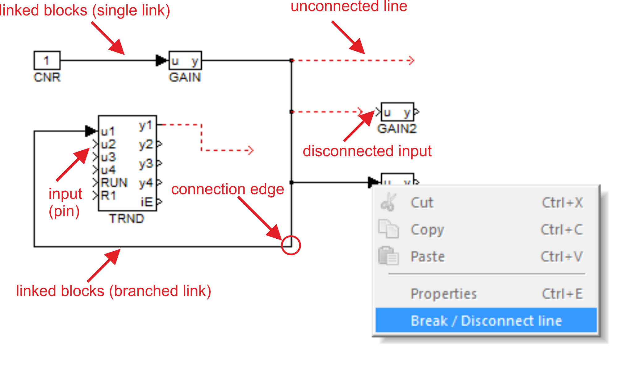
The blocks are connected by so-called connection lines or links. A link has always a single source and one or more sinks. A source may be any block output and a sink is any block input. It is not possible to connect two outputs together. A warning is shown during compilation when a source or sink of a link is not connected.
Links are created using the mouse by clicking on any input or output pin and holding the button pressed while moving towards another pin. A red dashed line is show until the final pin is reached. When the final pin is reached, a green bold line is shown. The line becomes a standard link after the mouse button is released.
A branch may be created by right clicking on any point of an existing link. A link may be deleted by pressing the Delete key when the link is selected. A link may be disconnected from a pin by right clicking on the pin and selecting Break/Disconect line from the context menu.
2.5 Persistent memory
REXYGEN supports permanent storage of function block parameters. Internal states of selected function blocks can be made persistent as well. Persistent memory performance is target platform specific. If the target platform does not have any supported persistent memory available, the permanent parameters will be stored to the permem.dat file by default (to the same directory as exec.rex is stored - \rex\rexcore on Linux targets or C:\ProgramData\REXControls\REX_<version>\RexCore\ on Windows targets).
In order to store the function block parameters, the checkbox Permanent in block properties must be checked. All function block parameters and also internal states in selected blocks will be stored (excluding arrays).
The list of function blocks with persistent internal states follows:
- INTE
- SINT
- COUNT
- SHIFTOCT
- OSD
- SHLD
- DIF_
- TIMER_
- ABSROT
- E/ATMT
Default save period is 300 seconds, default persistent memory size is 10240 byte.
The persistent memory can be reset or cleaned up using Download Dialog - see Fig. 3.1. Switch Download option in Download Dialog to Expert mode and choose between Reset persistent memory or Cleanup persistent memory. Reset persistent memory will replace entire persistent memory however Cleanup persistent memory will erase just the parameters which are not used any more.
Permanent storage file, its size, location and save period can be changed using configuration file rexcore.cfg. Find more details in the RexCore User Guide[2].
Be aware that the block parameters will be overwritten with the ones stored in persistent memory immediately after swapping executives if the Permanent option is enabled for the function block.
Chapter 3
Compile, Download and Diagnose Your Project
A project must be compiled and the resulting binary configuration has to be downloaded into the target device in order to put a control algorithm into operation. Both actions are performed directly from the REXYGEN Studio development tool.
3.1 Project Compilation
After an algorithm is designed, it is necessary to validate its structure, device configurations and block connections by compilation. The compilation results in a binary file called binary configuration which may be downloaded into a target device. The binary configuration is a platform/target independent file format with a .rex file name extension. The format of the binary configuration is optimized for fast-processing on a target device and has several consistency check mechanisms.
Warnings and errors may occur during a compilation. All warnings, errors and other various informational messages are print into the compiler console. A warning does not cause a termination of the compile process. But it should be observed carefully as it may probably indicate a problem that may lead into an unexpected behavior of the algorithm. All errors are treated as serious problems and cause a termination of the compiling process and no binary configuration is generated. All errors and warnings are indicated by theirs respective numbers and textual information message.
A compilation is started from the Compiler menu. A project is compiled by selecting Compiler/Compile from the menu, clicking on the icon on the toolbar or using the F5 shortcut.
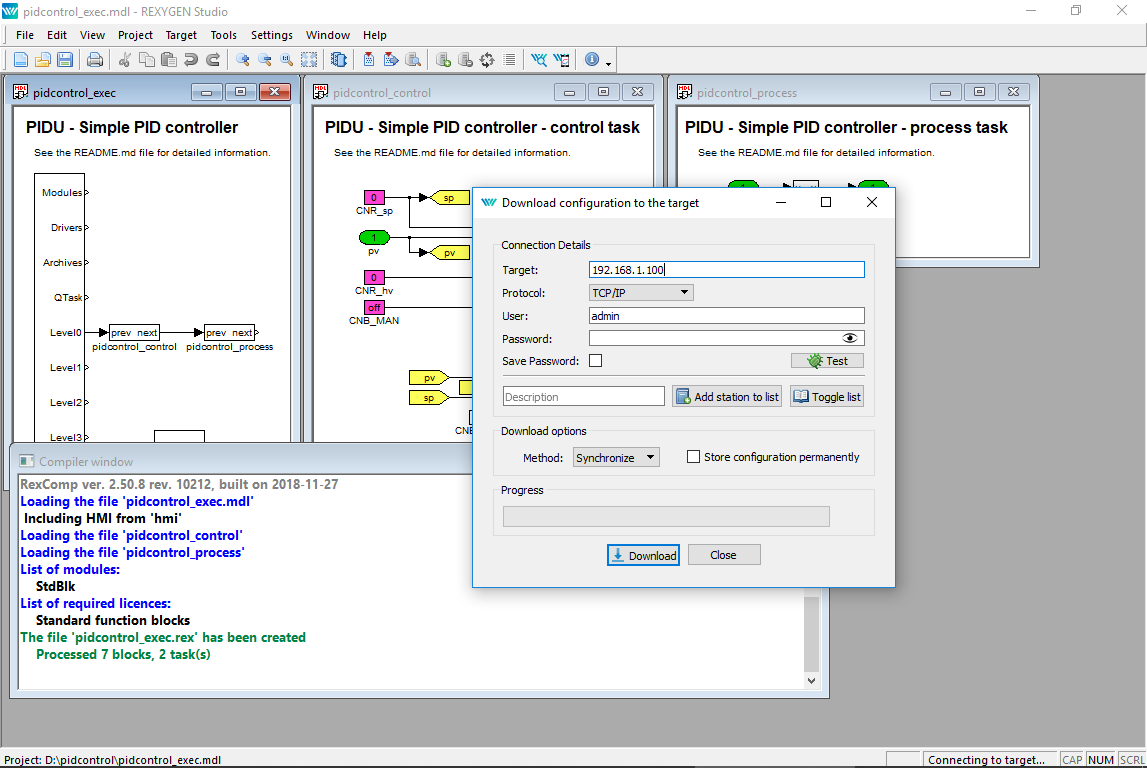
3.2 Downloading Project
A configuration is downloaded into the target device by selecting Compiler/Compile and Download from the menu, clicking on the icon on the toolbar or using the F6 shortcut.
A compilation of a project into a binary configuration is always performed before it is downloaded into the target device to ensure consistency. If an error occurs during the compilation, a compiler window is shown and the download operation is not available. A user must fix all errors indicated by the compiler before proceding with the download.
The download option Store configuration permanently is required to save the project configuration on the target device so that it gets loaded automatically when the target device boots up (e.g. after restart, powercycle, power loss, etc.).
3.3 License Activation
Before a binary configuration may be downloaded and activated the target has to be properly licensed. For a permanent target operation a full target license can be obtained from www.rexygen.com/pricing. A DEMO license is available for experiments and development. A DEMO license may be obtained directly from the REXYGEN Studio application while connecting to unlicensed target. A user may also get the DEMO license from the web page of the REXYGEN Controls company.
An information dialog about licensing is shown while connecting to an unlicensed target (figure 3.2). A user has the following three options:
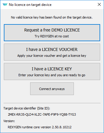
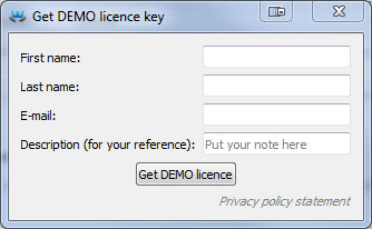
Get DEMO Licence: Select this option if you want to obtain a DEMO licence directly by filling-in name and email address to which a licensing key is sent (figure 3.3).
I already have a licence: Select this option if you already have a valid licence and you want to submit a licensing key into target device (figure 3.4).
Connect anyways: Select this option if you want to continue without licensing the target. But be aware that most of its functionality is not available without active licence.
3.4 Watch mode and Diagnostics
A comprehensive diagnostic tool is integrated directly into the REXYGEN Studio development tool. Before using the diagnostic tool, a binary configuration must be successfully downloaded into the target device. For information about downloading a binary configuration into the target device see the section 3.2.
A diagnostic tool in REXYGEN Studio may be used only when there is an active connection with the target device established. The connection is established by clicking on Target/Connect from the menu, clicking on the icon on the toolbar or using the F7 shortcut. The connection may also be established after a binary configuration is downloaded into the target device and a dialog is shown in which a user is asked if the connection with the target should be preserved and the so-called Watch mode should be activated.
A Watch mode is indicated by a gray background of all windows with function block diagrams. It is not possible to add, delete or move function block or connections between blocks in the Watch mode. Instead, a user may inspect and adjust signals of all block inputs, outputs and parameters and observe all signal values in real-time with a refresh period that may be adjusted in the Settings/Diadnostics Options dialog and which is one second by default.
3.4.1 Monitoring signals
It would be inefficient and bandwidth-consuming if all signals were monitored immediately when the Watch mode is activated. For that reason, only the DISPLAY blocks are monitored automatically. A user has to switch other function blocks into the so-called Monitoring State if signals of a particular block should be monitored.
When a block is in the Monitoring State, all input and output values are displayed at the corresponding pin of the monitored block. A block is added to the Monitoring State by selecting Project/Watch Selection from the menu or using the Ctrl+W shortcut. A block is removed from the Monitoring State by selecting Project/Exclude from Watch from the menu or using the Ctrl+Shift+W shortcut.
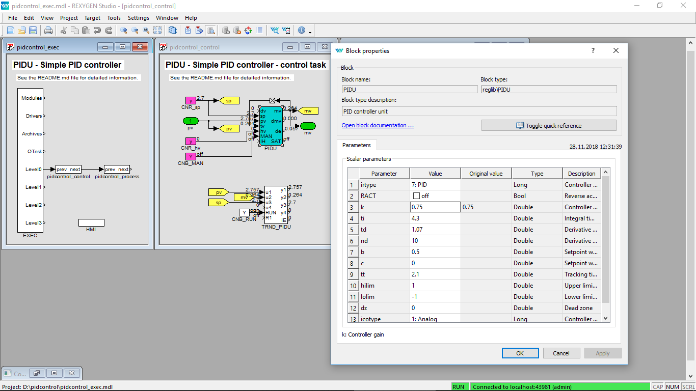
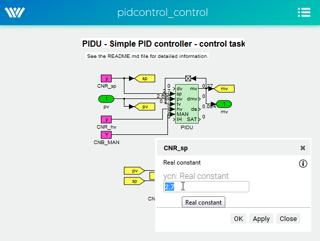
The values of parameters are shown in a floating yellow window when a user positions the mouse cursor over a function block. Parameters may also be inspected and adjusted from the on-line block properties dialog that is invoked by double-click or by pressing Ctrl+E. Be careful when modifying the values of parameters as changes are immediately committed to the target when the OK or Apply button is selected.
A dialog that allows to transfer all changes to the parameters made in the Watch mode back to the drawing is displayed before exiting Watch mode. A user may accept or discard changes to all parameters individually. This simplifies an effort to keep a project synchronized with the running configuration.
A user should always observe a right part of the status bar where a state of the connection with the target device is indicated. A green color indicates that connection is active and the data is communicated periodically without any errors. A red color indicates that the connection with the target device has been unexpectedly closed or an error occurred during the data exchange.
3.4.2 Viewing trends
The blocks TRND and TRNDV are available in REXYGEN to monitor signals over a period of time. The TRND allows to save up to 4 signals and the TRNDV allows to save up to 64 signals into the RAM memory of the target device. The samples are stored synchronously during a task execution. This allows to store and observe very fast processes without loosing a single sample.
The diagnostic tool of the REXYGEN Studio makes it possible to show all the data stored in the memory of the TRND block in the Watch mode. To show a windows with all data signals shown in a graphical trend simply double-click on a TRND block while the REXYGEN Studio is in the Watch mode. A data may be zoomed, a scale and a range of both axes may be changed and the data may also be exported do a CSV file from the window.
3.4.3 Viewing REXYGEN System Log
A system log with errors, warnings and other info messages with timestamps is present on every target device. A user may display a content of the system log directly from the REXYGEN Studio selecting Target/Show System Log from the menu or by clicking on the icon on the toolbar. A user may browse all messages, filter the content or export selected/all items to a CSV file.
The types and severities of messages that are written to the REXYGEN System log may be configured by selecting Target/Configure System Log from the menu. The Safe print flags to the target option must be selected if it is required to store the configuration of the system log permanently on the target device. A last saved configuration is loaded during the next system boot if the option remains unselected.
3.4.4 Diagnostics
A detailed diagnostics tool may be launched by clicking on Target/Diagnostics from the menu or by clicking on the icon on the toolbar.
The diagnostic tool window is closed automatically when REXYGEN Studio disconnects from the target device.
Chapter 4
Creating a Library of Reusable Components
In REXYGEN, creating reusable components is based on using the so-called subsystems. A subsystem is a container for a group of function blocks and their connections, which then appear as a single block. Nesting of subsystems is allowed, i.e. a subsystem can include additional subsystems. Any subsystem can be turned into a reusable component.
A reusable component can be created in 3 steps:
- Creation of a subsystem
- Declaration of subsystem parameters
- Moving the subsystem to a library
4.1 Creation of a Subsystem
There are two possible ways of creating a subsystem in REXYGEN Studio:
- Copy the SubSystem block from the INOUT library to the given diagram (.mdl file). Enter the subsystem by a double-click. Duplicate Inport and Outport blocks as needed. Insert function blocks as needed. Route the signals from Inports through function blocks to Outports. Rename Inports and Outports as needed.
- Select a group of blocks and use the Create subsystem command (in menu EditCreate subsystem). The selected blocks are then replaced a subsystem block, which contains all the original blocks and Inport and Outport blocks for signals crossing the subsystem boundary.
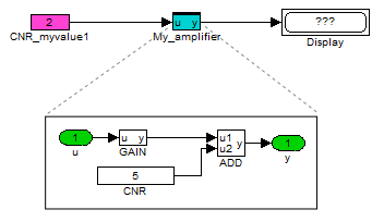
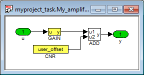
The resulting subsystem contains function blocks and their connections as shown in Figure 4.1.
4.2 Declaration of Subsystem Parameters
A typical requirement for a subsystem is to have parameters just like a standard function block to allow parametrization of its functionality.
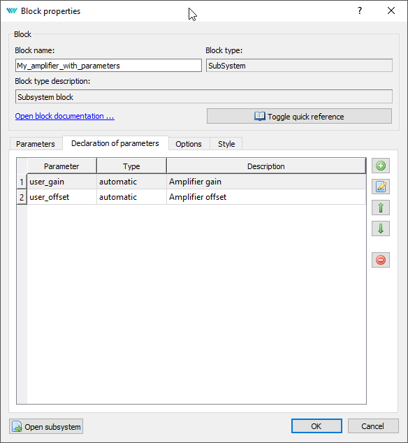
For this purpose the so-called subsystem parameters can be defined. The values of parameters can be used inside the subsystem. Each parameter also has a description of its meaning. To declare subsystem parameters, select one subsystem block and go to menu EditDeclaration of Parameters. A dialog appears (see Figure 4.2) and you can declare parameters and the corresponding descriptions.
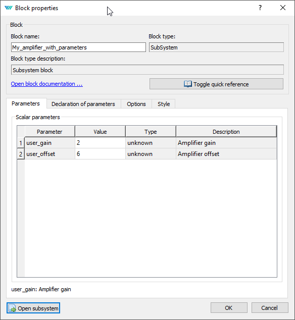
Once the parameters are declared, the subsystem acts just like any other block – double-click it to open the Block properties dialog. You can see the dialog contains the parameters which were declared (Figure 4.3).
Now you need to edit the internals of a subsystem with parameters. Select it and go to menu EditOpen Subsystem.
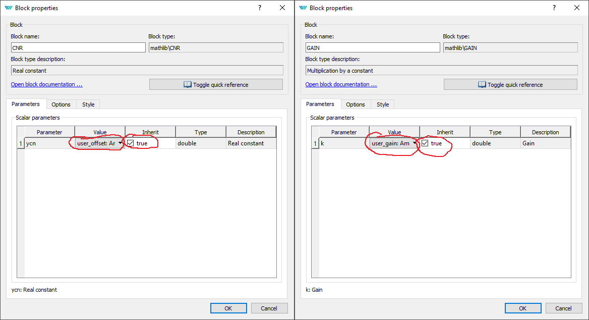
The function blocks inside a subsystem must be configured to accept the values of the declared parameters. To do so, open the Block properties dialog of individual function blocks, tick the Inherit checkbox and select the corresponding parameter (Figure 4.4).
The internals of the finished subsystem with parameters is shown in Figure 4.5.
In the end you are able to use the subsystem just like any other function block and you’ll find yourself configuring its behavior using the Block properties dialog. If everything works well, you might never go inside the subsystem again. If you need to debug your block or add new features/inputs/outputs, you can always Open Subsystem and do what’s needed.
Please refer to example project 0101-02 which demonstrates the use of subsystems. The example projects are a standard part of REXYGEN Studio.
4.3 Moving the Subsystem to a Library
Once you have your subsystem working, with or without parameters, chances are that you’ll want to use it in multiple tasks or projects. For such a purpose, you’ll create your own Library of subsystems. Your very own and problem-oriented library of reusable components.
To do so, create a new file in REXYGEN Studio and go to menu FileFile Type and change it to a Library.
Now you can fill your library with as many subsystems as you like. Just drag&drop subsystems to the library.
Afterwards save the library to the project folder. It is recommended to include ’library’ in the filename so you can easily recognize it later. The extension is .mdl, just like in other REXYGEN Studio files.
Once you close the library and open it again, you’ll notice its background is light blue and the library is in read-only mode. If you want to make some changes in the library, go to menu FileUnlock Library. This will make the library editable and you can do what is needed. Keep in mind that the changes you make will be applied to all files and projects referencing the library (we’ll get to that in chapter 5).
Note 1: The subsystems in the library can be standalone or they can be built on top of other subsystems from the same or from other user libraries.
Note 2: All files and projects referencing components in the library refer to the filename of the library. Renaming an existing library will lead to breaking references in all places. IT IS HIGHLY RECOMMENDED NOT TO RENAME A LIBRARY once you have started using its contents in your projects.
Chapter 5
Using User-Defined Libraries of Reusable Components
5.1 Including a Library in Your Project
When you have your own library ready (or when you want to use a 3rd party library of function blocks), you must include the library in your project. There are three ways to do so:
- Place the library (.mdl file) in the project folder.
- Include the PROJECT block in the project main file and configure its LibraryPath to point to the folder with the library. The path can be absolute or relative to the project folder.
- Define a global path to libraries in SettingsProgram Options. The path must be absolute.
5.2 Using Function Blocks From a Library
To use a function block from a library in your project, open the library like any other file in REXYGEN Studio and drag&drop function blocks to your project. This creates the so-called references to library blocks, which you can use just like all the native blocks of REXYGEN.
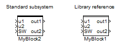
A library reference can be distinguished from a standard subsystem by the style of the upper border.
The difference from a standard subsystem (and the greatest benefit and the main purpose of a library reference) is that the content of the subsystem is given by the library. Therefore if you or anyone else update the library, the changes will be distributed to all subsystems referencing the library. To apply the changes in a project, you’ll need to open the project in REXYGEN Studio.
Please refer to example project 0101-03 which demonstrates the use of user-defined libraries. The example projects are a standard part of REXYGEN Studio.
Note: All files and projects referencing components in the library refer to the filename of the library. Renaming an existing library will lead to breaking references in all places. IT IS HIGHLY RECOMMENDED NOT TO RENAME A LIBRARY once you have started using its contents in your projects.
5.3 Detaching a Library Reference
In some cases you might need to break the link between the library reference and its origin. WARNING! This process is IRREVERSIBLE. This will turn the library subsystem into a standard subsystem. To do so, select the block and go to menu EditBreak Library Link. You’ll immediately notice that the upper border of the block is now a thick full line, indicating that the subsystem is no longer dependent on the library.
Chapter 6
Supported Operating Systems
All 32-bit and 64-bit Windows 7 and later operating systems are supported by development tools of REXYGEN. Windows Vista may also work but no guarantee nor support is provided for this version.
It is also possible to run all development tools on macOS or GNU/Linux on a 32-bit or 64-bit x86 platform using Wine from www.winehq.org. Although we test the development tools in Wine regularly, please note that this is meant for experienced users and only a very limited support is provided. You should have at least version 2.0 of Wine installed. The corefonts package must be installed using the command winetricks corefonts.
Chapter 7
Keyboard Shortcuts
| Keyboard shortcut | Function (as presented in the menu) |
| CTRL+N | New File |
| CTRL+O | Open File |
| CTRL+S | Save File |
| CTRL+P | |
| CTRL+SHIFT+S | Save as |
| CTRL+Z | Undo |
| CTRL+Y | Redo |
| CTRL+A | Select All |
| CTRL+X | Cut |
| CTRL+C | Copy |
| CTRL+V | Paste |
| CTRL+R | Rotate Block Clockwise |
| CTRL+SHIFT+R | Rotate Block Counterclockwise |
| CTRL+F | Find Function Block |
| CTRL+E | Properties |
| CTRL+M | Declaration of Subsystem Parameters |
| CTRL+U | Open Subsystem |
| CTRL+G | Create Subsystem |
| CTRL+L | Block Library |
| F2 | Zoom In |
| F3 | Zoom Out |
| F4 | Zoom Default |
| F1 | Help |
| F5 | Compile |
| F6 | Compile and Download |
| F7 | Connect |
| F8 | Disconnect |
| F9 | Activate/Deactivate Watch Mode |
| CTRL+W | Watch Selection |
| CTRL+SHIFT+W | Exclude from Watch |
Chapter 8
Other Important Features and Tools
8.1 Human-Machine Interface
Each target device running the RexCore contains an integrated webserver. The webserver and the webpages it provides may act as a Human-Machine Interface (HMI) for your application. The web interface with HMI may be opened from REXYGEN Studio by selecting Target/Web Interface in the menu.
Please refer to documentation of the HMI block in [1] on including the HMI in your project. All types of HMI supported by REXYGEN are described in [3].
8.2 REXYGEN HMI Designer
One of the approaches to creating a HMI for your application is to use the REXYGEN HMI Designer.
The REXYGEN HMI Designer may be started directly from the REXYGEN Studio by clicking on Tools/REXYGEN HMI Designer from the menu or by clicking on the icon on the toolbar. See [4] and [3] for details on using the REXYGEN HMI Designer.
8.3 REXYGEN Diagnostics
REXYGEN Diagnostics provides all the functionality which is available from the diagnostic tool in REXYGEN Studio, only as a stand-alone application.
REXYGEN Diagnostics may be started directly from REXYGEN Studio by clicking on Tools/REXYGEN Diagnostics from the menu or by clicking on the icon in the toolbar.
List of Figures
2.1 Function block library
2.2 Adding function blocks via Quick insert feature
2.3 Block Properties
2.4 Connection Between Blocks
3.1 Project Compilation and Download Dialog
3.2 Missing License Notification
3.3 DEMO License Dialog
3.4 Insertion of a Licensing Key
3.5 Monitoring and Diagnostics in the Watch Mode
4.1 Subsystem – A container for a group of function blocks
4.2 Subsystem – Declaration of parameters
4.3 Subsystem – User-defined parameters
4.4 Block properties dialog – Accept subsystem parameter
4.5 Subsystem with parameters – Internals of the finished subsystem
5.1 Standard subsystem vs. Library reference
8.1 WebWatch – Monitoring signals in a web browser
Bibliography
[1] REX Controls s.r.o.. Function blocks of REXYGEN – reference manual, 2020. .
[2] REX Controls s.r.o.. RexCore – User manual, 2020. .
[3] REX Controls s.r.o.. REXYGEN HMI – User manual, 2020. .
[4] REX Controls s.r.o.. Getting started with REXYGEN, 2020. .
Documentation reference number: 14711
2022 © REX Controls s.r.o., www.rexygen.com