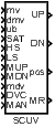
SCUV – Step controller unit with velocity input
Block SymbolLicensing group: STANDARD
Function Description
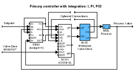
The block SCUV substitutes the secondary position controller SCU in the step controller loop
when the position signal is not available. The primary controller PIDU (or some of the derived
function blocks) is connected with the block SCUV using the block inputs mv, dmv and
SAT.
If the primary controller uses PI or PID control law (), then all three inputs mv, dmv and SAT of the block SCUV are sequentially processed by the special integration algorithm and by the three state element with parameters thron and throff (see the TSE block, use parameters , , and ). Pulse outputs of the three state element are further shaped in such a way that the minimum pulse duration time dtime and minimum pulse break time btime are guaranteed at the block outputs UP and DN. The parameter RACT determines the direction of motor moving. Note, the velocity output of the primary controller is reconstructed from input signals mv and dmv. Moreover, if the deviation error of the primary controller with (working in automatic mode) is less than its dead zone (), then the output of the corresponding internal integrator is set to zero.
The position pos of the valve is estimated by an integrator with the time constant trun. If signals from high and low limit switches of the valve are available, they should be connected to the inputs HS and LS.
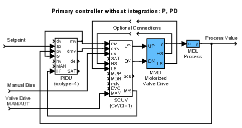
If the primary controller uses P or PD control law (), then the deviation error of the primary controller can be eliminated by the bias ub manually. In this case, the control algorithm is slightly modified, the position of the motor pos is used and the proper settings of thron, throff and the tracking time constant tt are necessary for the suppressing of up/down pulses in the steady state.
There is also a group of input signals for manual control available. The manual mode is activated by the input signal. Then it is possible to move the motor back and forth by the MUP and MDN input signals. It is also possible to specify a position increment/decrement request by the mdv input. In this case the request must be confirmed by a rising edge (offon) in the DVC input signal.
The overall control function of the SCUV block is obvious from the following diagram:
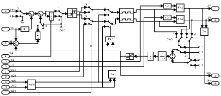
The complete structures of the three-state controllers are depicted in the following figures:
Inputs
mv | Manipulated variable (controller output) | Double (F64) |
dmv | Controller velocity output (difference) | Double (F64) |
ub | Bias (only for P or PD primary controller) | Double (F64) |
SAT | Internal integrator reset (connected to the SAT output of the primary controller) | Bool |
HS | Upper end switch (detects the upper limit position of the valve) | Bool |
LS | Lower end switch (detects the lower limit position of the valve) | Bool |
MUP | Manual UP signal | Bool |
MDN | Manual DN signal | Bool |
mdv | Manual differential value (requested position increment/decrement with higher priority than direct signals MUP/MDN) | Double (F64) |
DVC | Differential value change command (offon) | Bool |
MAN | Manual or automatic mode | Bool |
|
|
|
Outputs
UP | The "up" signal | Bool |
DN | The "down" signal | Bool |
pos | Position output of motor simulator | Double (F64) |
MR | Request to move the motor | Bool |
|
|
|
Parameters
thron | Switch-on value 0.0 0.02 | Double (F64) |
throff | Switch-off value 0.0 0.01 | Double (F64) |
dtime | Minimum width of the output pulse [s] 0.0 0.1 | Double (F64) |
btime | Minimum delay between two subsequent output pulses [s] 0.0 0.1 | Double (F64) |
RACT | Reverse action flag | Bool |
|
|
|
trun | Motor time constant (determines the time during which the motor position changes by one unit) 0.0 10.0 | Double (F64) |
CWOI | Controller without integration flag | Bool |
|
|
|
tt | Tracking time constant 0.0 1.0 | Double (F64) |
[Previous] [Back to top] [Up] [Next]
2022 © REX Controls s.r.o., www.rexygen.com