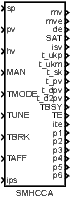
SMHCCA – Sliding mode heating/cooling controller with autotuner
Block SymbolLicensing group: AUTOTUNING
Function Description
The sliding mode heating/cooling controller (SMHCCA) is a novel high quality control algorithm
with a built-in autotuner for automatic tuning of the controller parameters. The controller is
mainly intended for temperature control of heating-cooling (possibly asymmetrical) processes
with ON-OFF heaters and/or ON-OFF coolers. The plastic extruder heating/cooling system is
a typical example of such process. However, it can also be applied to many similar cases, for
example, to thermal systems where a conventional thermostat is normally employed.
To provide the proper control function, the SMHCCA block must be combined with
the PWM block (Pulse Width Modulation) as depicted in the following
figure.
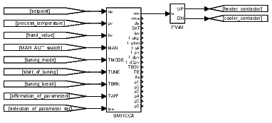
It is important to note that the block SMHCCA works with two time periods. The first period is the sampling time of the process temperature, and this period is equal to the period with which the block SMHCCA itself is executed. The other period is the control period with which the block SMHCCA generates the manipulated variable. This period is equal to the cycle time of PWM block. At every instant when the manipulated variable mv is changed by SMHCCA the PWM algorithm recalculates the width of the output pulse and starts a new PWM cycle. The time resolution of the PWM block is third time period involved in. This period is equal to the period with which the block PWM is executed and generally may be different from . To achieve the high quality of control it is recommended to choose as minimal as possible ( as maximal as possible), the ratio as maximal as possible but should be sufficiently small with respect to the process dynamics. An example of reasonable values for an extruder temperature control is as follows:
Notice however that for a faster controlled system the sampling periods , and must be shortened! More precisely, the three minimal time constant of the process are important for selection of these time periods (all real thermal process has at least three time constants). For example, the sampling period is sufficiently short for such processes that have at least three time constants, the minimal of them is greater than 10s and the maximal is greater than 100s. For the proper function of the controller it is necessary that these time parameters are suitably chosen by the user according to the actual dynamics of the process! If SMHCCA is implemented on a processor with floating point arithmetic then the accurate setting of the sampling periods , , and the parameter beta is critical for correct function of the controller. Also, some other parameters with the clear meaning described below have to be chosen manually. All the remaining parameters (xi, om, taup, taum, tauf) can be set by the built-in autotuner automatically. The autotuner uses the two methods for this purpose.
- The first one is dedicated to situations where the asymmetry of the process is not enormous (approximately, it means that the gain ratio of heating/cooling or cooling/heating is less than 5).
- The second method provides the tuning support for the strong asymmetric processes and is not implemented yet (So far, this method has been developed and tested in Simulink only).
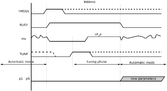
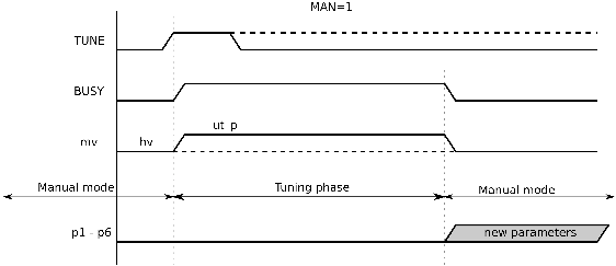
Despite the fact that the first method of the tuning is based only on the heating regime, the resulting parameters are usually satisfactory for both heating and cooling regimes because of the strong robustness of sliding mode control. The tuning procedure is very quick and can be accomplished during the normal rise time period of the process temperature from cold state to the setpoint usually without any temporization or degradation of control performance. Thus the tuning procedure can be included in every start up from cold state to the working point specified by the sufficiently high temperature setpoint. Now the implemented procedure will be described in detail. The tuning procedure starts in the tuning mode or in the manual mode. If the tuning mode () is selected the manipulated variable mv is automatically set to zero and the output TBSY is set to 1 for indication of the tuning stage of the controller. The cold state of the process is preserved until the initialization pulse is applied to the input TUNE (). After some time (depending on beta), when the noise amplitude is estimated, the heating is switched on with the amplitude given by the parameter ut_p. The process temperature pv and its two derivatives (outputs t_pv, t_dpv, t_d2pv) are observed to obtain the optimal parameters of the controller. If the tuning procedure ends without errors, then TBSY is set to 0 and the controller begins to work in manual or automatic mode according to the input MAN. If and affirmation input TAFF is set to 1, then the controller starts to work in automatic mode with the new parameter set provided by the tuner (if , then the new parameters are only displayed on the outputs p1..p6). If some error occurs during the tuning, then the tuning procedure stops immediately or stops after the condition pv>sp is fulfilled, the output TE is set to 1 and ite indicate the type of error. Also in this case, the controller starts to work in the mode determined by the input MAN. If then works in automatic mode with the initial parameters before tuning! The tuning errors are usually caused either by an inappropriate setting of the parameter beta or by the too low value of sp. The suitable value of beta ranges in the interval (0.001,0.1). If a drift and noise in pv are large the small beta must be chosen especially for the tuning phase. The default value (beta=0.01) should work well for extruder applications. The correct value gives properly filtered signal of the second derivative of the process temperature t_d2pv. This well-filtered signal (corresponding to the low value of beta) is mainly necessary for proper tuning. For control, the parameter beta may be sometimes slightly increased. The tuning procedure may be also started from manual mode () with any constant value of the input hv. However, the steady state must be provided in this case. Again, the tuning is started by the initialization pulse at the input TUNE () and after the stop of tuning the controller continues in the manual mode. In both cases the resulting parameters appear on the outputs p1,...,p6.
The control law of the block SMHCCA in automatic mode () is based on the discrete dynamic sliding mode control technique and special 3rd order filters for estimation of the first and second derivatives of the control error.
The first control stage, after a setpoint change or upset, is the reaching phase when the dynamic sliding variable
is forced to zero. In the above definition of the sliding variable, denote the filtered deviation error and its first and second derivatives in the control period , respectively, and are the control parameters described below. In the second phase, is hold at the zero value (the sliding phase) by the proper control "bangs". Here, the heating action is alternated by cooling action and vice versa rapidly. The amplitudes of control actions are adapted appropriately to guarantee approximately. Thus, the hypothetical continuous dynamic sliding variable
is approximately equal to zero at any time. Therefore the control deviation behaves according to the second order differential equation
describing so called zero sliding dynamics. From it follows that the evolution of can be prescribed by the parameters . For stable behavior, it must hold . A typical optimal value of ranges in the interval and about is often a satisfactory value. The optimal value of strongly depends on the controlled process. The slower processes the lower optimal . The recommended value of for start of tuning is .
The manipulated variable mv usually ranges in the interval . The positive (negative) value corresponds to heating (cooling). For example, means the full heating. The limits of mv can be reduced when needed by the controller parameters hilim_p and hilim_m. This reduction is probably necessary when the asymmetry between heating and cooling is significant. For example, if in the working zone the cooling is much more aggressive than heating, then these parameters should be set as and . If we want to apply such limitation only in some time interval after a change of setpoint (during the transient response) then it is necessary to set initial value of the heating (cooling) action amplitude u0_p (u0_m) to the suitable value less than hilim_p (hilim_m). Otherwise set and .
The current amplitudes of heating and cooling uk_p, uk_m, respectively, are automatically adapted by the special algorithm to achieve so called quasi sliding mode, where the sign of alternately changes its value. In such a case the controller output isv alternates the values and . The rate of adaptation of the heating (cooling) amplitude is given by time constant taup (taum). Both of these time constants have to be sufficiently high to provide the proper function of adaptation but the fine tuning is not necessary. Note for completeness that the manipulated variable mv is determined from the action amplitudes uk_p, uk_m by the following expression
Further, it is important to note that quasi sliding is seldom achievable because of a process dead time or disturbances. The suitable indicator of the quality of sliding is again the output isv. If the extraordinary fine tuning is required then it may be tried to find the better value for the bandwidth parameter beta of derivative filter, otherwise the default value is preferred.
In the manual mode () the controller input hv is (after limitation to the range ) copied to the manipulated variable mv. The controller output mve provides the equivalent amplitude-modulated value of the manipulated variable mv for informative purposes. The output mve is obtained by the first order filter with the time constant tauf applied to mv.
Inputs
sp | Setpoint variable | Double (F64) |
pv | Process variable | Double (F64) |
hv | Manual value | Double (F64) |
MAN | Manual or automatic mode | Bool |
|
|
|
TMODE | Tuning mode | Bool |
TUNE | Start the tuning experiment: TUNE offon | Bool |
TBRK | Stop the tuning experiment: TBRK offon | Bool |
TAFF | Affirmation of the parameter set provided by the tuning procedure: | Bool |
ips | Meaning of the output signals p1,…,p6 | Long (I32) |
|
|
|
Outputs
mv | Manipulated variable (controller output) | Double (F64) |
mve | Equivalent manipulated variable | Double (F64) |
de | Deviation error | Double (F64) |
SAT | Saturation flag | Bool |
|
|
|
isv | Number of the positive () or negative () sliding variable steps | Long (I32) |
t_ukp | Current amplitude of heating | Double (F64) |
t_ukm | Current amplitude of cooling | Double (F64) |
t_sk | Discrete dynamic sliding variable | Double (F64) |
t_pv | Filtered process variable pv by 3rd order filter | Double (F64) |
t_dpv | Filtered first derivative of pv by 3rd order filter | Double (F64) |
t_d2pv | Filtered second derivative of pv by 3rd order filter | Double (F64) |
TBSY | Tuner busy flag () | Bool |
TE | Tuning error | Bool |
|
|
|
ite | Error code | Long (I32) |
|
|
|
pi | Identified parameters with respect to ips, | Double (F64) |
Parameters
ipwmc | PWM cycle (in sampling periods of the block, ) 100 | Long (I32) |
xi | Relative damping of sliding zero dynamics 0.58.01.0 | Double (F64) |
om | Natural frequency of sliding zero dynamics 0.00.01 | Double (F64) |
taup | Time constant for adaptation of heating action amplitude [s] 700.0 | Double (F64) |
taum | Time constant for adaptation of cooling action amplitude [s] 400.0 | Double (F64) |
beta | Bandwidth parameter of the derivative filter 0.01 | Double (F64) |
hilim_p | Upper limit of the heating action amplitude 0.0 1.0 1.0 | Double (F64) |
hilim_m | Upper limit of the cooling action amplitude 0.0 1.0 1.0 | Double (F64) |
u0_p | Initial amplitude of the heating action 1.0 | Double (F64) |
u0_m | Initial amplitude of the cooling action 1.0 | Double (F64) |
sp_dif | Setpoint difference threshold for blocking of heating/cooling amplitudes reset 10.0 | Double (F64) |
tauf | Time constant of the filter for obtaining the equivalent manipulated variable 400.0 | Double (F64) |
itm | Tuning method 1 | Long (I32) |
|
|
|
ut_p | Amplitude of heating for tuning experiment 0.0 1.0 1.0 | Double (F64) |
ut_m | Amplitude of cooling for tuning experiment 0.0 1.0 1.0 | Double (F64) |
[Previous] [Back to top] [Up] [Next]
2022 © REX Controls s.r.o., www.rexygen.com