1-Wire driver for the REXYGEN system
(the OwsDrv module)
User guide
Plzeň (Pilsen), Czech Republic
2022-11-22
Contents
1.1 Introduction
1.2 System requirements
1.3 Installation of the driver on the host computer
1.4 Installation of the driver on the target device
1.4.1 Running the 1Wire server
2 Including the driver in the project
2.1 Adding the OwsDrv driver
2.2 Connecting the signals in the algorithm
3 Driver configuration
3.1 Configuration dialog
3.2 Use of alarms of the owfs program
3.3 Special signals
4 Troubleshooting
Chapter 1
The OwsDrv driver and the REXYGEN system
1.1 Introduction
This manual describes the OwsDrv driver for data exchange between the REXYGEN system and various devices supporting the 1-Wire protocol [1]. The OwsDrv driver relies on the OWFS 1-Wire File System [2], namely the owserver module.
It is possible to communicate with any device supported by the OWFS.
1.2 System requirements
In order to use the driver, the host computer (development) and the target computer (runtime) must have the following software installed:
|
Host computer |
|
|
Operating system |
one of the following: Windows 7/8/10 |
|
REXYGEN system |
version for Windows operating system |
|
Target device |
|
|
REXYGEN system |
runtime core for GNU/Linux |
|
IO driver |
version for GNU/Linux |
|
OWFS |
version for GNU/Linux |
|
|
|
|
|
|
1.3 Installation of the driver on the host computer
The OwsDrv driver is included in the installation package of the Development tools of the
REXYGEN system. It is necessary to select the corresponding package in the installer. The
REXYGEN system typically installs to the
C:\Program Files\REX Controls\REX <version> folder.
The following files are copied to the installation folder:
- Bin\OwsDrv_H.dll – Configuration part of the OwsDrv driver.
- Doc\PDF\ENGLISH\OwsDrv_ENG.pdf – This user manual.
1.4 Installation of the driver on the target device
If there is no RexCore runtime module installed on your target device, install it first using the Getting started guide of the REXYGEN system for the corresponding platform[3].
In order to communicate with the 1-Wire devices from the REXYGEN system it is necessary
to install the owserver and ow-shell packages of the OWFS suite and the 1-Wire driver of
the REXYGEN system, which is done by the following command:
Debian:
sudo apt-get install owserver ow-shell rex-owsdrvt
1.4.1 Running the 1Wire server
The owserver must be configured to use the 1-Wire bus master of your choice. Use sudo nano /etc/owfs.conf command to edit the file.
E.g. for use with USB to 1-Wire adapter (e.g. DS9490R):
allow_other
server: port = localhost:4304
server: usb = all
timeout_volatile = 2
For I2C devices based on the DS2482-100 or DS2482-800 chip the /etc/owfs.conf file should contain the following:
allow_other
server: port = localhost:4304
server: i2c=ALL:ALL
timeout_volatile = 2
It is also necessary to activate the I2C bus and enable the i2c-dev kernel module. If you have used our installation scripts for your platform, everything is ready for you. If you have not, you probably know what to and how to do it. In any case, just check that e.g. /dev/i2c-1 is present.
Restart the owserver and list the detected 1-Wire devices by the owdir command. The output should look like this:
/bus.1
/bus.0
/uncached
/settings
/system
/statistics
/structure
/simultaneous
/alarm
The first line is the 1-Wire device ID (the DS18B20 temperature sensor in this case). Read the
temperature by issuing the command:
owread /28.551DDF030000/temperature12
(change the ID to match your device).
Chapter 2
Including the driver in the project
The driver is included in the project as soon as the driver is added to the project main file and the inputs and outputs are connected in the control algorithms.
2.1 Adding the OwsDrv driver
The project main file with the OwsDrv driver included is shown in Figure 2.1.
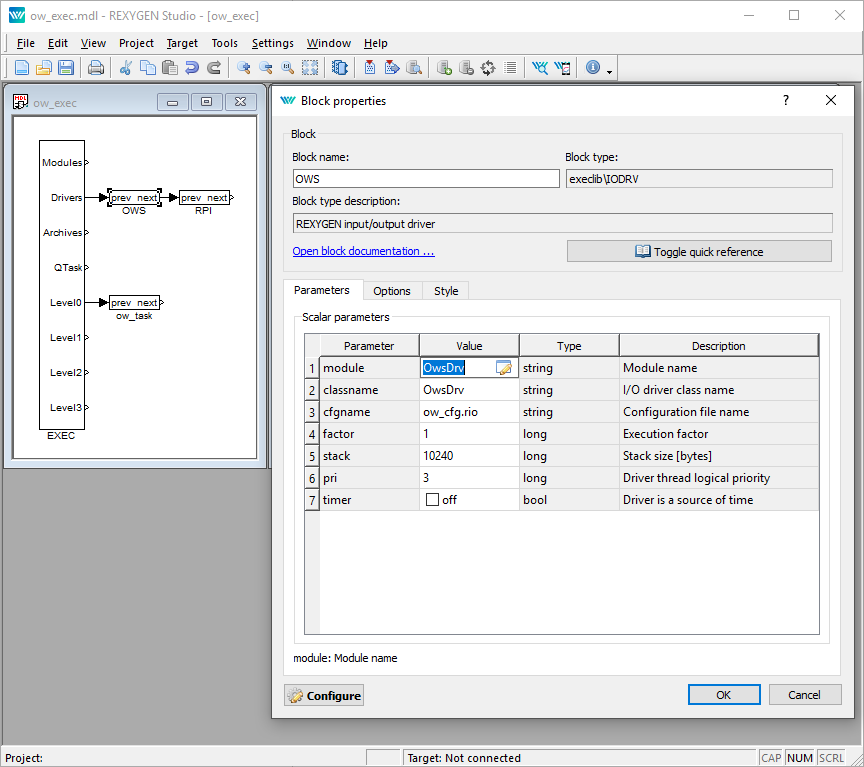
There is one block which must be added to the project to include the driver. A block of type IODRV renamed to OWS and connected to the Drivers output of the main EXEC block. The name of this block (OWS, see Fig. 2.1), is the prefix of all input and output signals provided by this driver. The three most important parameters are:
- module – Name of the module linked to the driver, in this case OwsDrv. The name is CASE SENSITIVE!
- classname – Class of the driver, in this case OwsDrv. The name is CASE SENSITIVE!
- cfgname – Name of the driver configuration file (*.rio, REXYGEN Input/Output). It is a simple text file which is automatically created when necessary. It can have arbitrary name (here ow_cfg.rio). The configuration is further discussed in chapter 3.
The name of this block (OWS, see Fig. 2.1), is the prefix of all input and output signals provided by this driver.
The above mentioned parameters of the IODRV function block are configured in REXYGEN Studio program. The configuration dialog is shown also in Fig. 2.1.
2.2 Connecting the signals in the algorithm
The input and output signals of the driver must be interconnected with the individual tasks (.mdl files). The individual tasks (QTASK or TASK blocks) are connected to the QTask, Level0,…, Level3 outputs of the main EXEC block.
The inputs and outputs of the OwsDrv driver can be accessed as shown in Fig. 2.2.
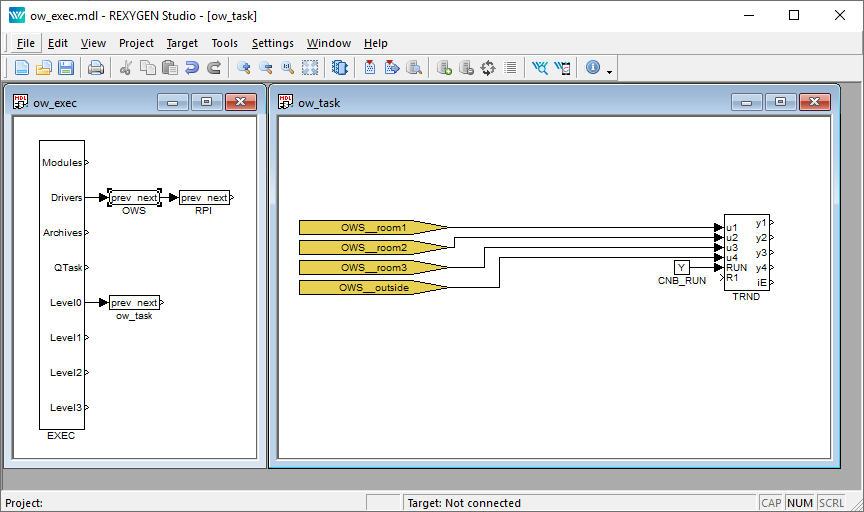
The From block allowing the user to read one input signal has the Goto tag set to OWS__temperature. The Goto block allowing the user to set one output signal would have the Goto tag set to OWS__name. The blocks always have the OWS prefix right at the beginning of the tag followed by two _ characters (underscore).
Chapter 3
Driver configuration
This chapter describes the configuration of individual input and output signals and their symbolic naming. The signals are mapped to individual variables of the OWFS server.
3.1 Configuration dialog
The configuration dialog shown in Fig. 3.1 is part of the OwsDrv_H.dll file. It can be activated from REXYGEN Studio by pressing the Configure button in the parameters dialog of the IODRV block (see chapter 2).
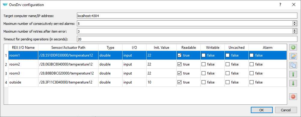
The upper part of the dialog defines the connection to the owserver. The owserver typically runs on the same machine as RexCore but it is not a rule.
The individual signals to read or write from the REXYGEN control algorithm are defined in the lower part of the configuration dialog. Simply add the signals, use the device IDs displayed by the owdir command.
For an output signal (in the I/O column the output is selected), the Value is once written to the output if it is not overwritten from the control algorithm.
The signal table in the driver configuration dialog is processed cyclically during the run-time in the following way. Each output signal which has been changed since the last write is written with the value. Similarly, all input signals are being cyclically read in the same order. When a large number of inputs is configured the reading of the whole table can take quite a long time. Therefore, the owserver program allows to indicate signal changes as so called alarms in the /alarm directory, see section 3.2. This driver is able to process alarms from REXYGEN version 2.5.
Moreover, if the Uncached option is checked then the given signal will be always read directly from the connected integrated circuit (e.g. from the thermometer). If the Uncached is not checked then the returned value will be read from the cache memory which is typically updated each 15 seconds. Note: The more signals has chosen Uncached, the slower the response of this driver.
To optimize the performance of this driver it is helpful to know how the driver operates internally. The main loop activated each period of the driver always handles no more than one request to the owserver program and after sending a request to owserver, it does not wait on an immediate response (ie. If the response data are not available, it tries to get them in the next loop run). After initializing the driver (when the real/time executive is running) the main loop operates as follows:
- It check whether the currently processed request (from the previous call of this loop) has been completed.
- If so, it starts to process alarms (for details see next section).
- If no alarm is processed, it tries to write a single output value from the control algorithm.
- If no write is processed, it tries to read one input value to the control algorithm.
The above procedure shows that the highest importance (priority) has alarm processing, then writing the output values from the algorithm, and the lowest reading signals. In frequent occurrence of alarms (which is not normal) it could happen that writting and reading requests are not served at all (this effect is also called starvation). Therefore, it is possible to set the maximum number of consecutive served alarms in the driver configuration in Fig. 3.1. After this number of served alarms, the first of the other pending requests (writing or reading items) is processed.
3.2 Use of alarms of the owfs program
Work with alarms belongs among the advanced techniques and requires good knowledge of owfs and the owserver. It is recommended to use alarms only when the 1-Wire driver response is too slow.
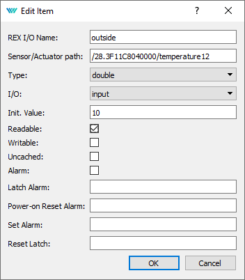
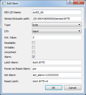
Configuration of one alarm in the case of DS2408 circuit based 1-Wire device is shown in Fig. 3.3. The path to the signal (Sensor/Actuator path) is entered without starting directory /alarm. After selecting the Alarm, additional strings should be entered. The configured string values are preprocessed and stored to working string variables for each alarm (before start of the driver):
- sPath – path to the device, here: /29.066418000000. For reading or writing values, the /alarm directory can be inserted before this path, and the character / and the value of some of the preprocessed strings (see next items) can be appended after this path
- sSensed – file with the value to be read, here: sensed.BYTE
- sLatch – file with the sensed value change flag(s), here: latch.BYTE
- sAlarmPor – file indicating the power-on reset of the device, here: por
- sSet – file, to which should be written the configuration of next alarm generation (first part of the Set Alarm item to the character =), here: set_alarm
- sSetVal – value, which should be written to the sSet file (second part of the Set Alarm item from the character =), here: 133333333
- sLatchRes – file, to which should be written the value indicating that the alarm has been served (first part of the Reset Latch item to the character =), here: latch.BYTE
- sLatchResVal – value, which should be written to the sLatchRes file (second part of the Reset Latch item from the character =), here: 0
The OwsDrv uses a state machine with the following states for the alarm processing:
- NOT_USED – The driver configuration does not contain any alarm.
- INIT – The initial state of the state machine.
- ALARM_DIR – Browsing the /alarm directory contents.
- ALARM_PROCESS – Start of each alarm processing.
- ALARM_POR_READ – Detecting whether the device did not perform the power-on reset initialization by reading a file whose name is stored in the sAlarmPor string.
- ALARM_POR_READ_WAIT – Waiting for the completion of the reading started in the ALARM_POR_READ state.
- ALARM_SET – Setting the alarm generated on the device after power-on reset. The string value in sSetVal is written into the file whose name is specified by the sSet string.
- ALARM_SET_WAIT – Waiting for the completion of the writing started in the ALARM_SET state. After that, all outputs are checked. When an output whose path starts with the sPath string is found, the initial value specified in the Init. Value item is written to the corresponding file (see fig. 3.3).
- ALARM_INIT_WRITE_WAIT – Waiting for the completion of each individual initial value writing started in the previous state.
- ALARM_POR_RESET – Clearing of the power-on reset initialization flag. The value 0 is written into the file whose name is specified by the sAlarmPor string.
- ALARM_POR_RESET_WAIT – Waiting for the completion of the power-on reset flag clearing.
- ALARM_LATCH – Determining whether the device indicates the occurrence of an alarm. In this state, the file whose name is specified by the sLatch string is read. If the content is non-zero, or the list of items contains at least one non-zero, the occurrence of alarm since the last reading is detected.
- ALARM_LATCH_WAIT – Waiting for the completion of the reading started in the ALARM_LATCH state.
- ALARM_SENSED – Reading the signal after the alarm occurred. If the alarm occurrence has been detected in the ALARM_LATCH state, reading of the file whose name is specified by the sSensed string in the /alarm directory is started.
- ALARM_SENSED_WAIT – Waiting for the completion of the reading started in the ALARM_SENSED state.
- ALARM_LATCH_RESET – Clearing of the alarm occurence flag. The string value in sLatchResVal is written into the file whose name is specified by string sLatchRes in the /alarm directory.
- ALARM_LATCH_RESET_WAIT – Waiting for the completion of the alarm occurence flag clearing started in the ALARM_LATCH_RESET state.
- SENSED – Reading the signal, which could change before clearing the alarm occurence flag in the ALARM_LATCH_RESET state. In this state, reading the contents of the file whose name is specified by the sSensed string is started.
- SENSED_WAIT – Waiting for the completion of the reading started in the SENSED state.
- ALARM_BYPASS – State enabling to perform one write or read of another signal between processing of two alarms.
Transitions between states follows the rules in table 3.1. The first column shows the current state, the second column can contain one or more conditions for each current state, and the third column contains the state into which the state-machine goes, if the relevant condition of the second column is fulfilled. Conditions in column two are evaluated from top to bottom for each current state.
| # | State | Transition Conditions | New State |
| -1 | NOT_USED | At least one configured alarm found | INIT |
| 0 | INIT | Start of reading the /alarm directory | ALARM_DIR |
| 1 | ALARM_DIR | Reading of the /alarm directory completed | ALARM_PROCESS |
|
2 |
ALARM_PROCESS | If nMaxConsAlarms is consecutively read then | ALARM_BYPASS |
| else | ALARM_POR_READ | ||
| At the end of alarm cycle assign: iAlarmPos = -1. Then | ALARM_BYPASS | ||
|
3 |
ALARM_POR_READ | If sAlarmPor is not defined then next alarm | ALARM_PROCESS |
| If sAlarmPor is empty then | ALARM_LATCH | ||
| After succesful read of sAlarmPor | ALARM_POR_READ_WAIT | ||
|
4 |
ALARM_POR_READ_WAIT | If the variable por is not equal to zero | ALARM_SET |
| If por is equal to zero | ALARM_LATCH | ||
|
5 |
ALARM_SET | If sSet or sSetVal is not defined then next alarm | ALARM_PROCESS |
| If sSet or sSetVal is empty then | ALARM_POR_RESET | ||
| Assign iAlarmInitPos = -1; After successful write | ALARM_SET_WAIT | ||
|
6 |
ALARM_SET_WAIT | Iterate iAlarmInitPos. For found write commands | ALARM_INIT_WRITE_WAIT |
| At the end of the cycle: iAlarmInitPos = -1; then | ALARM_POR_RESET | ||
|
7 |
ALARM_INIT_WRITE_WAIT | If iAlarmInitPos < 0 then | ALARM_POR_RESET |
| else | ALARM_SET_WAIT | ||
|
8 |
ALARM_POR_RESET | If sAlarmPor is not defined then next alarm | ALARM_PROCESS |
| If sAlarmPor is empty then | ALARM_LATCH | ||
| After successful write | ALARM_POR_RESET_WAIT | ||
| 9 | ALARM_POR_RESET_WAIT | After competion the request | ALARM_LATCH |
|
10 |
ALARM_LATCH | If sLatch is not defined or is empty then next alarm | ALARM_PROCESS |
| After successful reading | ALARM_LATCH_WAIT | ||
|
11 |
ALARM_LATCH_WAIT | If the variable latch is not equal to zero then | ALARM_SENSED |
| else next alarm | ALARM_PROCESS | ||
|
12 |
ALARM_SENSED | If sSensed is not defined then next alarm | ALARM_PROCESS |
| If sSensed is empty then | ALARM_LATCH_RESET | ||
| After successful reading | ALARM_SENSED_WAIT | ||
| 13 | ALARM_SENSED_WAIT | After competion the request | ALARM_LATCH_RESET |
|
14 |
ALARM_LATCH_RESET | If sLatchRes or sLatchResVal is not defined then | ALARM_PROCESS |
| If sLatchRes or sLatchResVal is empty then | SENSED | ||
| After successful write | ALARM_LATCH_RESET_WAIT | ||
| 15 | ALARM_LATCH_RESET_WAIT | After competion the request | SENSED |
|
16 |
SENSED | If sSensed is not defined or is empty then next alarm | ALARM_PROCESS |
| After successful reading | SENSED_WAIT | ||
| 17 | SENSED_WAIT | After competion the request | ALARM_PROCESS |
|
18 |
ALARM_BYPASS | If iAlarmPos >= 0 then next alarm | ALARM_PROCESS |
| Else continue from the beginning | INIT | ||
3.3 Special signals
In some cases, it is useful/necessary to access the status or configuration variables of the driver. The signals below marked with the R (W) letter are readable (writeable) signals, i.e. they are inputs (outputs) of the control system.
The driver performs these special signals:
| _DGNRESET | W | reset of the accumulated diagnostics information |
| _TRANSACTIONS | R | total number of transactions with owserver |
| _RECONNECTS | R | number of reconnections (after communication errors) |
All global signals starts with the _ (underscore) character. In these cases the tripple underscore will be used (e.g. OWS___DGNRESET) because of the __ (double underscore) separator between the diver tag and the signal name.
Moreover, each signal can be suffixed with a special text which determines that a special attribute of the signal will be used instead of the signal value. The special suffixes are the following (all begins with _):
| _Value | RW | alias for signal value |
| _DGNRESET | W | reset of the diagnostics information for the given signal |
| _TRANSACTIONS | R | number of transactions with owserver for the given signal |
| _ReadEnable | RW | enable to read the signal; equivalent: _RE |
| _WriteEnable | RW | enable to write the signal; equivalent: _WE |
| _WriteOneShot | W | one-shot write of the signal; equivalent: _WOS |
| _Alarm | R | alarm flag of the signal; after reading it is cleared |
| _PerFactor | R | driver period multiplier for the signal update |
| _PerCount | R | number of the driver periods from the last signal update |
| _PerMax | R | maximum number of the driver periods between two consecutive signal updates |
| _PendCount | R | current number of waiting cycles for returning the value from owserver |
| _PendLast | R | last number of waiting cycles for returning the value from owserver |
| _PendMax | R | maximum number of waiting cycles for returning the value from owserver |
| _Period | R | update period (in seconds) of the signal |
| _Age | R | the time elapsed since the last update of the signal (signal age) |
| _AgeMax | R | maximum signal age from the last reset of the diagnostics information |
Chapter 4
Troubleshooting
In the case that the diagnostic tools of the REXYGEN system (e.g. REXYGEN Diagnostics) report unexpected or incorrect values of inputs or outputs, it is desirable to test the functionality outside the REXYGEN system (command line tools, simple Python script, etc.). Also double check the configuration – the most common problems include:
- Hardware problem – incorrect wiring
- Kernel modules for I2C or USB devices are not loaded
- Incorrect device ID
- Too long period of a task reading signals from OwsDrv (the system log contains regularly the Socket Error). It is necessary to increase the owserver timeout by the command line parameter --timeout_server=60 (timeout increased to 60 seconds)
In the case that the given input or output works with other software tools and does not work in the REXYGEN system, report the problem to us, please. E-mail is preferred, reach us at support@rexygen.com. Please include the following information in your description to help us process your request as soon as possible:
- Identification of the REXYGEN system you are using. Simply export it to a file using the REXYGEN Diagnostics program (Target Licence Export).
- Short and accurate description of your problem.
- The configuration files of the REXYGEN system (.mdl files) reduced to the simplest case which still demonstrates the problematic behavior.
Bibliography
[1] Maxim Integrated. 1-Wire Application Notes. http://www.maximintegrated.com, 2013.
[2] Paul Alfille. OWFS 1-Wire Filesystem. http://www.owfs.org, 2013.
[3] REX Controls s.r.o.. Getting started with REXYGEN on Raspberry Pi, 2020. .
Documentation reference number: 14711
2022 © REX Controls s.r.o., www.rexygen.com