


Turning Raspberry Pi into a PLC - Adding a pushbutton
This is a tutorial for an outdated version of the REX Control System. Please follow the up-to-date Getting started guides listed below:
In the first tutorial on using the Raspberry Pi as a PLC the process of compiling, downloading and monitoring the control algorithm using the tools of the REX Control System was illustrated.
This tutorial will follow with modification of the hardware setup and control algorithm to include a simple pushbutton. This pushbutton will control the blinking of the red LED. The red LED will be blinking only when the button is pressed, otherwise it will be in its default state.
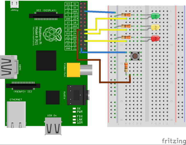
- The hardware part of the modification is very easy, you just need to wire up the pushbutton and a protective resistor (R=330Ω) between GND and GPIO#22.
- The software part also needs a minor modification to read the state of the pushbutton. Start with the project files from the previous tutorial and open them in RexDraw. Opening the blink_exec.mdl file will do the trick, the blink_task.mdl will be opened automatically.
- Save the exec file into a separate folder buttonblink and name it buttonblink_exec.mdl.
- Save the task file into the same folder and name it buttonblink_task.mdl.
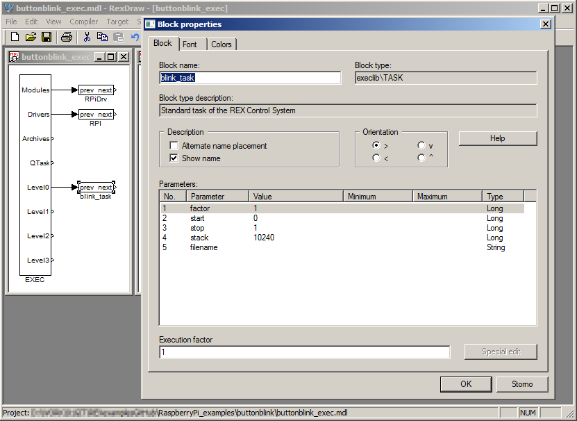
- In the exec file, double-click the block named blink_task and rename it to buttonblink_task.mdl. By that you are linking the executive configuration with the task.
- For reading the pushbutton in the algorithm, open the Block library (View->Block Library) and find the block named From.
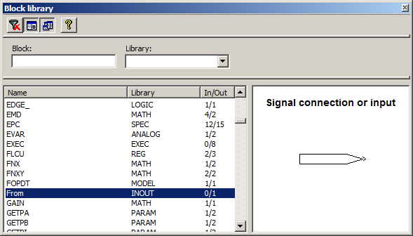
- Now drag&drop it into the task file.
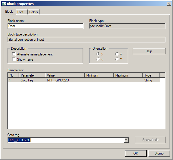
- In the task file, double-click the From block and enter RPI__GPIO22U into the Goto tag parameter. By that, you are telling the Raspberry Pi driver to read data from the GPIO#22 pin. The trailing U enables the internal pull-up resistor of the pin to avoid floating of the pin when the button is not pressed.
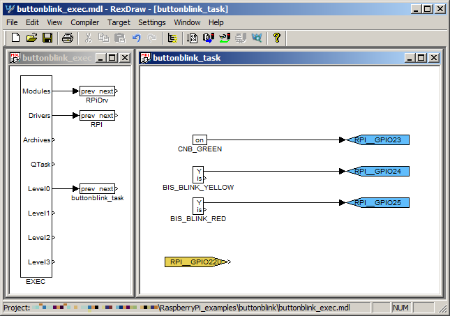
- Switch to Colors tab and select the background color of the From block. It is a good practice to mark the physical inputs and outputs by color.
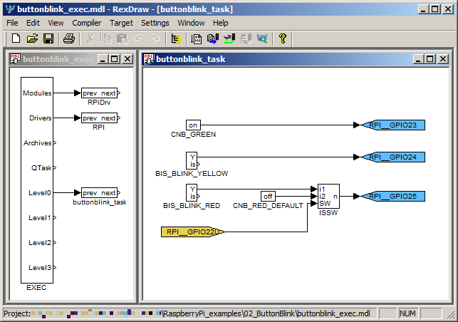
- Your project should now look like the one below.
- Now delete the line between the BIS_BLINK_RED block and the output flag of GPIO pin 25 by left-clicking it and hitting the Delete button on your keyboard.
- We will be switching between the default and blinking state of the red LED, therefore we add the ISSW block from the library. This block implements a simple switch for integer and Boolean signals.
- We will also need to define the default state of the red LED, therefore we add a Boolean constant (the CNB block) and rename it to CNB_RED_DEFAULT. Also uncheck the YCN checkbox, the red LED will be off by default.
- The signal from the button will be switching the signal sent to the GPIO#25, therefore connect the input flag to the SW input of the ISSW block.
- Also connect the n output of the ISSW block to the flag for output GPIO#25.
- When the button is pressed, the GPIO pin is held LOW and the input value is 0. When released, the pin is held HIGH and the input is 1. Therefore connect the Y output of the BIS block to the i1 input of the ISSW block (active when SW=0) and the CNB_RED_DEFAULT block to the i2 input (active when SW=1).
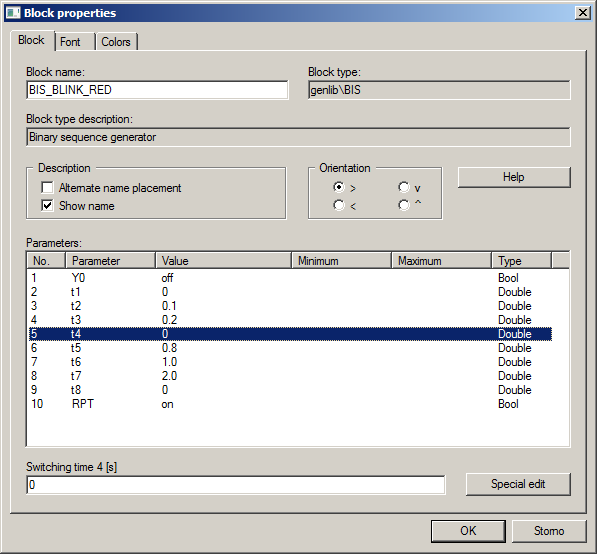
- The last modification is changing the blinking pattern of the red LED. Doble-click the BIS_BLINK_RED block and change the parameters: t2=0.1, t3=0.2 and t4=0. By that we define a binary signal with 5 Hz frequency.
- Now you can compile the project and download it to your Raspberry Pi.
- You will probably want to watch the algorithm, namely the ISSW block.
- The green LED should be glowing, the yellow LED should blink each 2 seconds and the red LED should be inactive upon the download.
- As soon as you press the pushbutton, the ISSW block switches the signals and the red LED should start to blink with frequency of 5 Hz.
- Now you can play a bit with the parameters of individual blocks to achieve e.g. blinking patterns of your own. You can change the parameters in online mode or you can change them in the source files of the project and compile&download the algorithm to Raspberry Pi again. Remember that the default parameters which will be used after Raspberry Pi reboot are the ones which were used during compilation of the project.
- When changing the blinking patterns, do not forget to take into account the sampling period of the algorithm, which is 20 ms in this example (this is defined by the tick and ntick0 parameters of the EXEC block). Unless you change the EXEC configuration, you cannot generate pulses shorter than 20ms.
What is this good for in real world?
By manipulating GPIO pins you can control relays, which can switch lights, pumps, ventilators, heaters, refrigerators, etc. Reading pushbuttons allows you to create simple user interfaces. Follow our tutorial on pool automation to see how you can benefit from what you have learned.
Troubleshooting
Got stuck at any point? We want to hear about it, do let us know.
Additional information
You can also:
- Download the project files from GitHub. You can download only the buttonblink_exec.mdl and buttonblink_task.mdl files, however, it is strongly recommended to download the whole repository of examples in the form of a standard .zip file. The files are located in the RaspberryPi_examples\02_ButtonBlink folder. If you are familiar with Git and GitHub server, you will probably use the direct link to the REX Control System examples repository.
- Read the Getting started guide and watch our Getting started video which both explain a PID control loop example.
- Explore the rich function block library of the REX Control System.
- Visit the Raspberry Pi Foundation webpage, where you can find more information about the Raspberry Pi minicomputer.
Raspberry Pi is a trademark of the Raspberry Pi Foundation.
updated: 2017-05-19